Plant Symbol Lineweights
- Important: Read This Section Before Running BatchMan
- Changing Plant Symbol Lineweights With BatchMan
- Saving and Accessing Your Changes
- Re-Creating Your Custom Plant Symbols Using Our Default Blocks
- Related Webinars
After reviewing our plant symbols, you may decide that some of the lineweights within these symbols are too thick or too thin for your standards. You can use our Batchman batch file management tool to change some or all of the symbols' lineweights at a time.
To review the typical lineweights used by our software for plant symbols, view the appendix of the Planting Getting Started Guide PDF. The appendix includes samples of each category of plant symbol, and at different scales, with Trees and Shrubs on different tabs.
Important: Read This Section Before Running BatchMan
Here are a few important recommendations about BatchMan:
- We recommend running BatchMan from a blank file.
- If you do run BatchMan from a working drawing, it will discard the current file open and not save changes. Make sure you save changes to the file before running BatchMan.
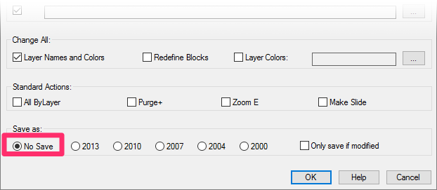
- Once you've configured BatchMan to make a set of changes, don't forget to select one of the Save as options at the bottom of the dialog box before clicking OK – if you want to save your changes.

- You can leave the No Save option selected if you only want to preview the changes, but keep in mind that your changes will not be saved unless you select a version of AutoCAD to use when saving the changes.
Changing Plant Symbol Lineweights With BatchMan
In CAD, lineweight (or line thickness) is tied directly to layer color. Therefore, to change the lineweight in a symbol, you'll need to change its layer colors. You can do so on multiple blocks at a time using our BatchMan tool.
After determining a lineweight change that suits your preferences or office standards, open BatchMan:

F/X Admin ribbon, BatchMan button
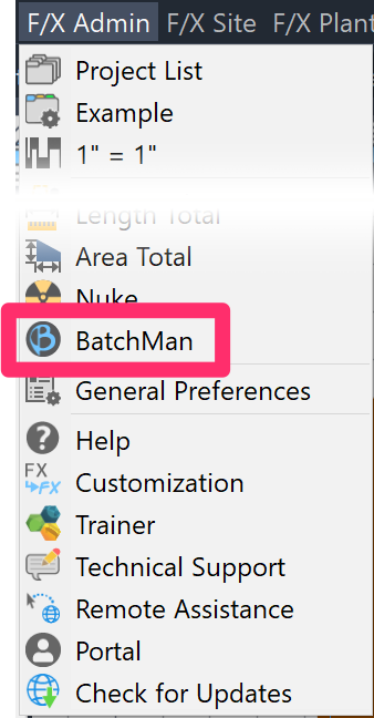
F/X Admin pull-down menu, BatchMan option
or type BatchMan in the Command line
The BatchMan dialog box will open. Click Add Folder + Subfolders.
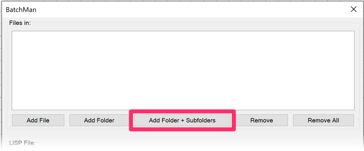
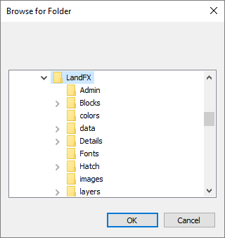
In the Browse for Folder dialog box, navigate to and select the folder containing the symbols whose lineweights you want to change.
Click OK.
Back in the BatchMan dialog box, a list of all files in the folder you selected will now appear in the Files in: pane.
-
Check one of the following boxes:
- Layer Names and Colors
- Layer Colors (if you want to change the layer colors but keep their names the same)
- Under Save As, select the option for the version of CAD you'd like to use when saving your edited symbols.
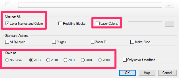
Remember: You can select No Save if you want to preview your changes but aren't ready to save them. However, keep in mind that your changes will not be saved unless you select a version of AutoCAD.
Click OK to change layer names and/or colors within the symbol block files you've selected. Allow a few minutes for BatchMan to compile the symbol files. The Change All Layers dialog box will then open.
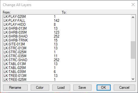
Here, you'll see a list of all layer names and colors in the files you've selected.
Our lineweight convention is to list the lineweight by millimeters in the name of the layer – for example, 013M represents 0.13 mm.
Highlight the name of a layer you want to edit by changing its name and/or color.
Changing a Layer Name
To change the name of a layer, highlight it and click Rename.
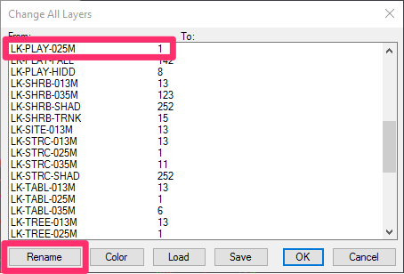

Enter a new name for the layer in the New Layer Name dialog box, then click OK.
(In this case, enter the name of an existing layer that has your desired lineweight.)
Changing a Layer Color
To change the color of a highlighted layer, click Color.
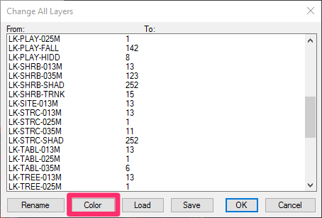
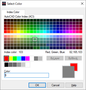
Select a new layer color in the Select Color dialog box, then click OK. (In this case, select the color of an existing layer with your desired lineweight.)
An Example:
Let's say you decide the line colors in a particular symbol are too thick. In this case, you'll need to highlight the layers with thicker lines and change them to layers with thinner lines.
For instance:
- Highlight the layer LK‑TREE‑050M (which will plot at 0.50 mm, or 0.020 in) and change its name and color to the next thinnest layer. In this case, the next-thinnest layer is LK‑TREE‑035M (which will plot at 0.35 mm, or 0.014 in). Click the Rename button to change the name of the layer LK-TREE-050M to LK-TREE-035MM. Click the Color button to change the color of the layer LK-TREE-050M.
- Continue to select layers containing LK-TREE-(SIZE) lines and change them to layers with thinner lines. Or stop with the lineweights that concern you the most.
Notes:
- Don’t alter the LK-(PLANT TYPE) portion of any layer name (example: LK-TREE). Just change the ending identifier. For example, simply change LK-TREE-050MM to LK-TREE-035MM, as shown above.
- It’s best to rename and assign a new color to a layer, rather than just change the color. This method will help you avoid possible miscommunications or problems later.
- You can change any number of layers to the same layer if you wish.
- The shadow layers (example: LK-TREE-SHAD*) and screened line layers (example: LK-TREE-SM*) can also be altered if desired.
- Try to leave the LK-TREE-TRNK or LK-SHRUB-TRNK layers alone; they should not be moved or renamed.
Saving and Accessing Your Changes
Whether you've changed layer colors or names, or both, it's a good idea to save your changes in the Change All Layers dialog box by clicking Save.
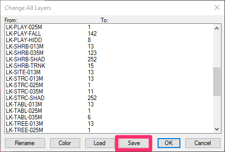
If you've selected Change Layer Names and Colors in the BatchMan dialog box, your changes will be saved as an LCF file.

If you've selected Layer Colors in the BatchMan dialog box, your changes will be saved as a GCL file.
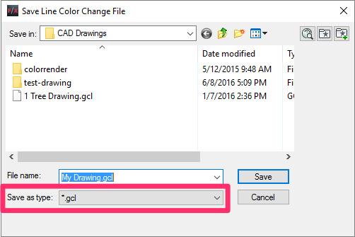
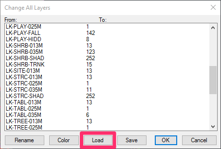
You can access your GCL files at any time using either BatchMan or our Change Layer Colors tool.
In either case, click Load in the Change All Layers dialog box.
Browse to your desired GCL file in the Load Line Color Change File dialog box, and click Open.
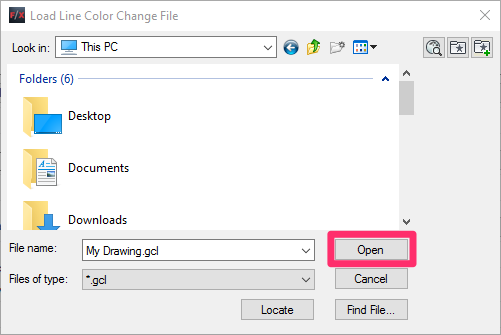
The layer settings from the selected GCL file will be applied to the drawing you currently have open.
Re-Creating Your Custom Plant Symbols Using Our Default Blocks
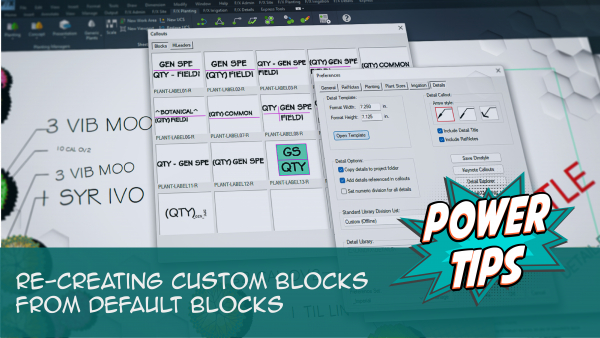
Has something gone wrong with any of your custom plant symbol blocks? We recommend using our default blocks as a basis for your custom blocks, as they're already set up correctly for best performance in CAD. Use them to repair or re-create your custom blocks.
See our Re-Creating Custom Blocks from Default Blocks Power Tip, linked to the right, for more information and instructions.
Related Webinars
- Rock Out With Your Block Out: We’ve formulated a workflow that incorporates Adobe Photoshop and Illustrator along with AutoCAD to create custom block content. Learn how to transform an image into a polished, optimized, and unique block for your library. (1 hr 5 min)
- Planting F/X Setup: If you're trying to make Planting F/X work with your firm's existing style standards, this webinar is for you. (58 min)


