Customize Concept Graphics
As with many of the other Land F/X blocks, the Nodes and Concept Lines in our Concept Graphics library are fully customizable. You can update these items by opening and editing the corresponding source block files in your LandFX folder.
The Concept Graphics source files are stored in the following subfolders within the folder LandFX\Blocks\Graphics\Concept:
- Arrows: Source blocks for the arrows that are placed at the ends of Concept Lines)
- Lines: Source blocks for the Concept Line styles
- Nodes: Source blocks for the Concept Nodes styles

To customize one of the Concept Graphic styles, open the DWG file associated with that style.
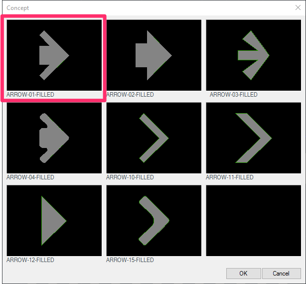
For example, you may want to make changes to the arrow with the name ARROW-01-FILLED.
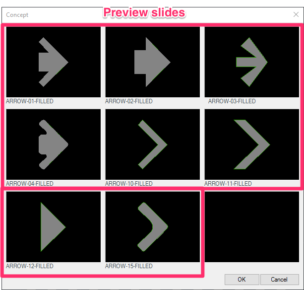
In this case, you would open the source block file LAFX-ARROW-01-FILLED.dwg in the folder LandFX\Blocks\Concept\Arrows and make your changes directly in the source file. You'll also want to create a new slide file (the file of the same name ending in .sld) to display in the arrows dialog box pictured above.
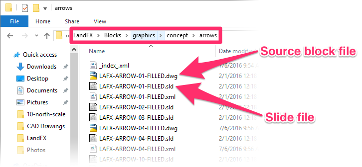
Note that the block and slide filenames need to end with "-FILLED." Also note the naming of the layer used for the color fill pattern.
Concept Graphics are highly customizable, so you don't need to use our Save Block tool to save them once you've made changes. You can also use commands such as Copy, Save As, or Write Block (WBLOCK) to move one of the existing blocks to a new file and save it as a completely new Concept Graphic Style.
Use the AutoCAD Insert command (type INSERT in the Command line) to place any copied blocks in a new drawing. This command will ensure the insertion point is set correctly. If not, open the file, type INSBASE in the Command line, and set it.
Once you've made your changes, you can either save over the original file or save your new file in the same folder but with a new name. Just make sure the filename ends with FILLED.
Determining the Number of Available Styles for Each Graphic Type
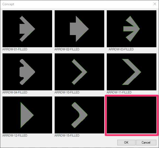
Keep in mind that the number of graphics you'll be able to select and place will be limited by the construction of the various Concept dialog boxes. Each one has a set number of black rectangles. Each black denotes an available space for a new style of that type of graphic.

For example, the dialog box for selecting a Node style has two black rectangles, meaning you can create and select two new Node styles.
The dialog box for selecting an arrow for one extra arrow style.
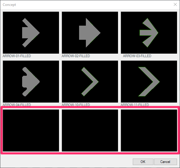
If necessary, you can delete the source files of a few styles of one of the Concept Graphics to make room for more extra styles.
For example, if you delete two of the arrow source files from the folder LandFX\Blocks\Graphics\Concept\Arrows, the arrows dialog box will have two additional spaces, allowing you to create and select two additional arrow styles of your own.
Once you've created a customized Concept Graphic, it's time to create a preview slide to display in the selection dialog box for that graphic type.
1. Open the file you've edited and saved.
2. Resize the AutoCAD window to approximately the same size and ratio of the target preview slide (yes, very tiny – it will look rather funny).
3. Type UCSICON in the Command line and press Enter to activate the UCS icon command. You can type OFF and press Enter to turn it off.
4. Type -SHADE and press Enter.
5. Type MSLIDE and press Enter.
6. Repeat these steps for each DWG file you've edited to create a new graphic style.
Your new Concept Graphics are now ready to use!


