How Does Irrigation F/X Calculate Rotor Precipitation Rates?
Issue
You've sized your rotor zones, and the station precipitation rates don't line up with either:
- The manufacturer's catalog, or
- Your manual cross-check calculations
Cause
Our calculation of rotor precipitation rates works a little differently from our calculation of the other irrigation emission types. The Land F/X system does a bit more automation on attempting to calculate whether the zone incorporates triangular or square spacing based on where the heads are placed in the design. As a result, you might see some variation of precips per zone that can't be explained – even with the same type of equipment and flows.
Solution
Our rotor precipitation rates are no secret. We offer the ability to view the calculations and how they are applied to a rotor zone through tools we've created. The first tool is a command called FXDEBUG. To run this command, type FXDEBUG in the Command line and press Enter.
You'll now see the status F/X Debug Mode ON in the Command line.

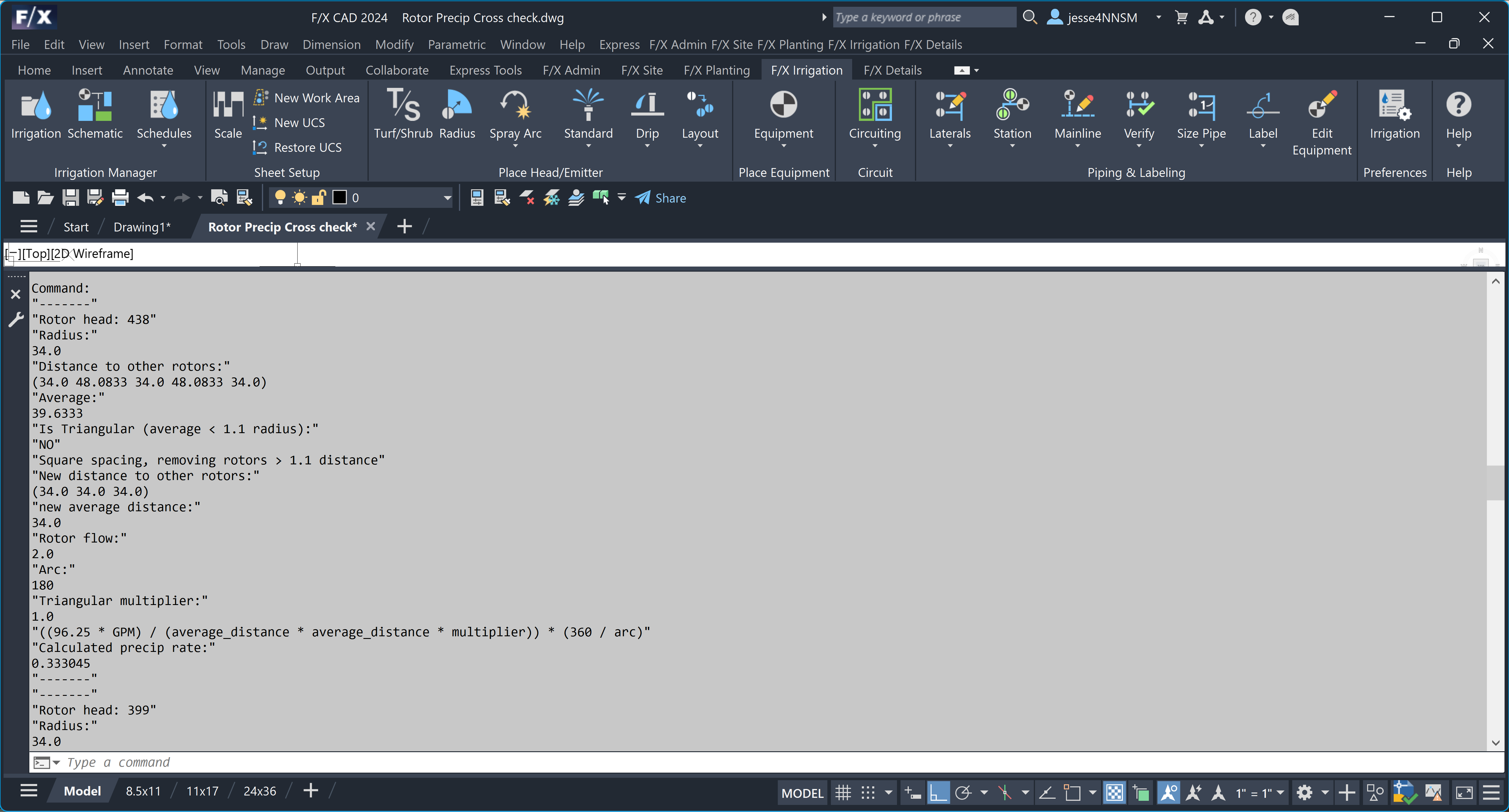
At this point, you can size a rotor zone as normal and view the real calculations used. After sizing the valve, pull up the Command line to view the calculations. In the example below, we can see the first rotor head being calculated is tagged as Rotor head 438.
It would be helpful to identify which head is which. We can label the heads with their system tags through another tool and command. To access the rotor head label tool, first type LOL in the Command line and press Enter. Then type EH and press Enter.

You'll be prompted to Select piped entity.
You can now select rotor heads and place a leader with text containing the rotor head's label.
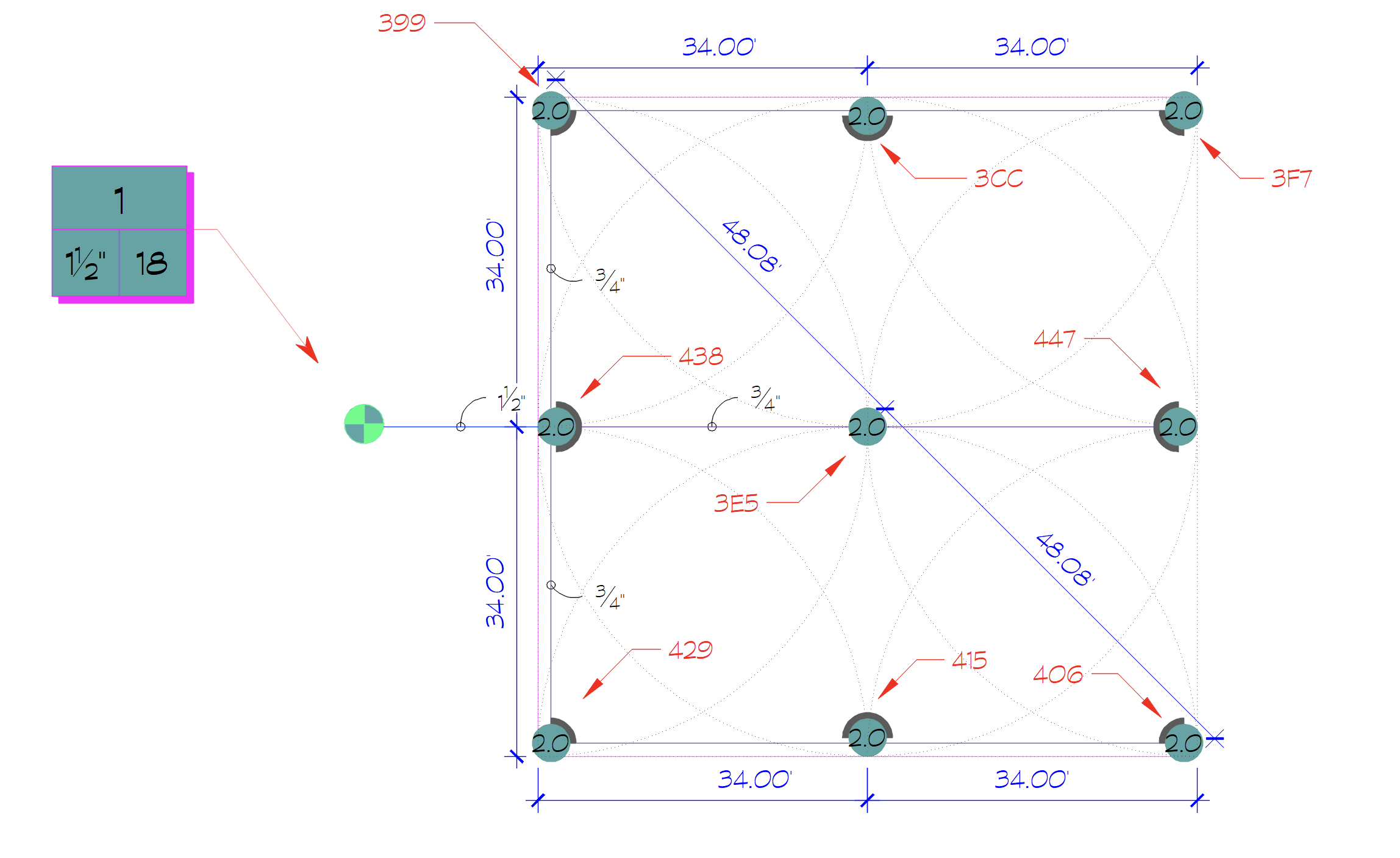
Let's apply these tools to rotor zones that are laid out in square spacing, triangular spacing, and an irregular pattern according to manufacturer precipitation rates.
Keep in mind that the precipitation rates found in catalogs and performance charts are based on certain conditions that are not always found in the layouts created in an actual site design. This is why we find it important to calculate each rotor head individually based on its data and its relation to the nearby rotors in the zone, and then take the average of the precipitation rates of all heads in the zone and use that as the zone precipitation rate.
Example 1: Rotors with square spacing
Below is an example section of the performance chart for the Hunter PGP Ultra I-20 standard blue nozzle.
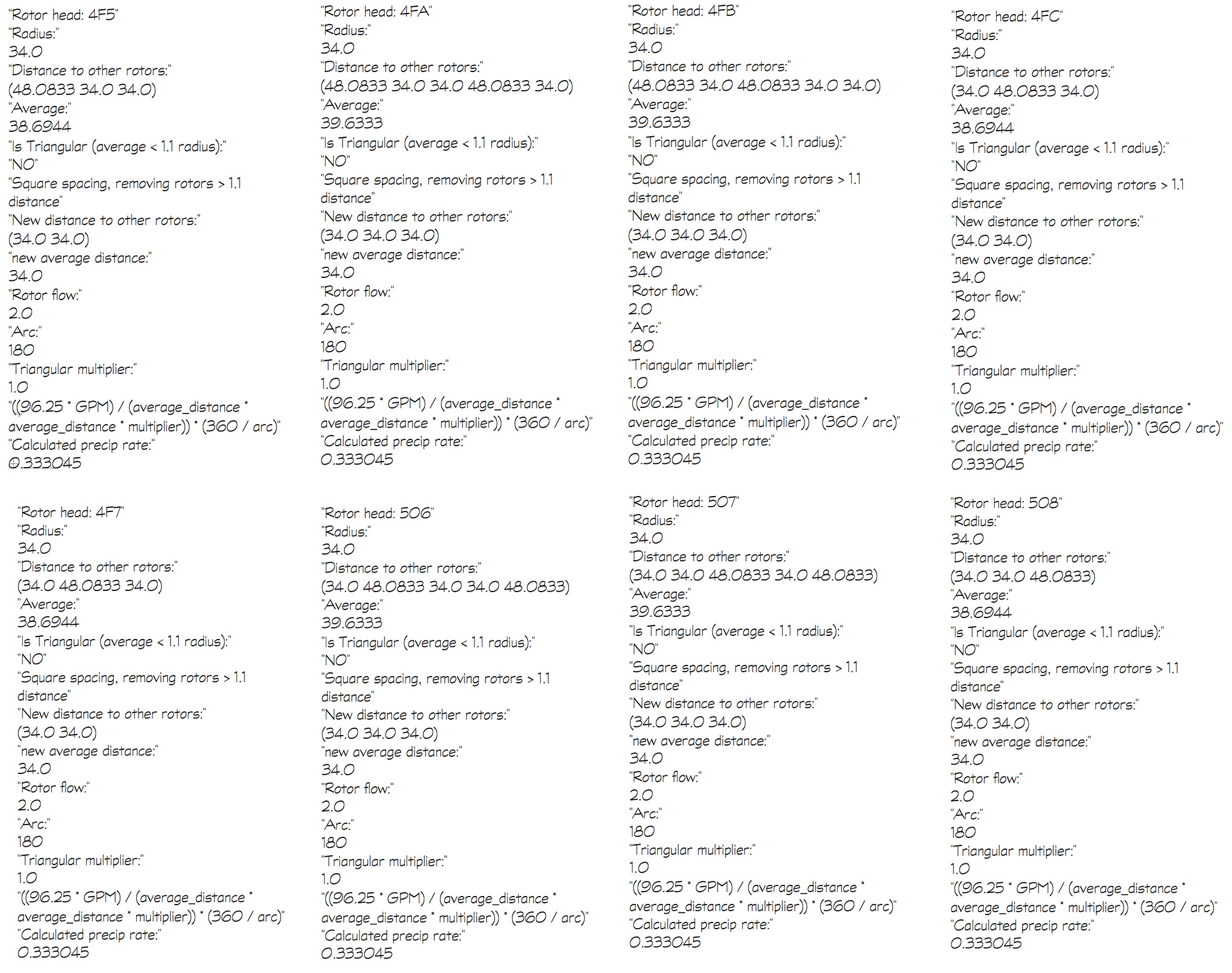
The example shows a rotor zone laid out to match the layout Hunter uses to calculate the precipitation rate for square spacing. We can see that at exact spacing, a rotor zone consisting of entirely 180-degree spray arcs has a precipitation rate calculated in Land F/X that matches the manufacturer numbers.
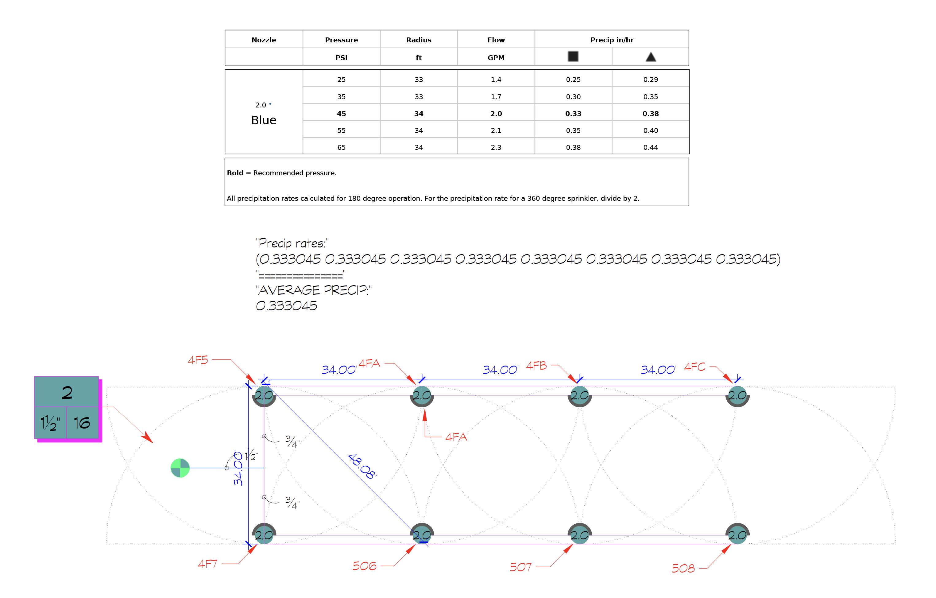
Our rotor zone precipitation rates comprise the average precipitation rates of all heads comprising the rotor zone. Let's break down the calculations for Rotor head 4F5. First, the distances to nearby rotors are measured. The average of those distances is used to determine whether the spacing is square or triangular. We classify the spacing for the rotor as being triangular if the average distance to nearby rotors is less than 1.1 times the radius of the rotor being calculated. In this case, 1.1 x 34 = 37.4, so the average of 38.6944 is greater than 37.4. To calculate the square spacing, nearby rotors with distances greater than 37.4 (1.1 x 34) are removed. Another average distance is calculated with the remaining nearby rotors. The remaining values we use in the precipitation rate calculation, such as the rotor flow and spray arc degrees, are listed next. These are all inserted into our rotor precipitation rate formula.
((96.25 x GPM) / (Average distance x average distance x triangular multiplier)) x (360/arc)

Example 2: Rotors with triangular spacing
Below is an example of the same Hunter rotors laid out with triangular spacing.
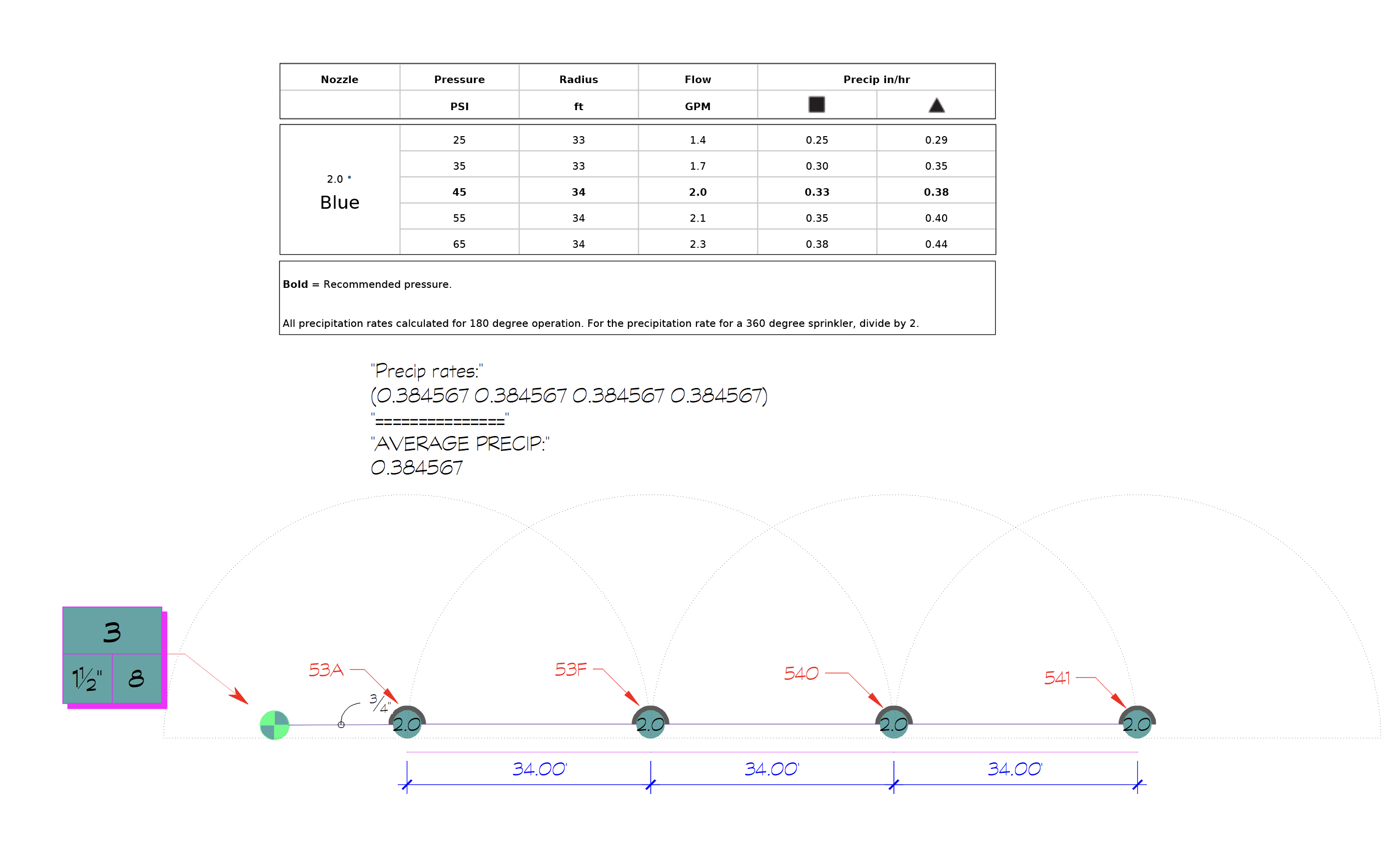

For the first head on the zone, Rotor head 53A, the spacing is determined to be triangular because the average distance to the nearest heads, 34, is less than 1.1 times the radius of the head (1.1 x 34 = 37.4). This spacing prompts the use of our triangular multiplier, 0.866025.
Close
Example 3: Rotors laid out in an irregular pattern
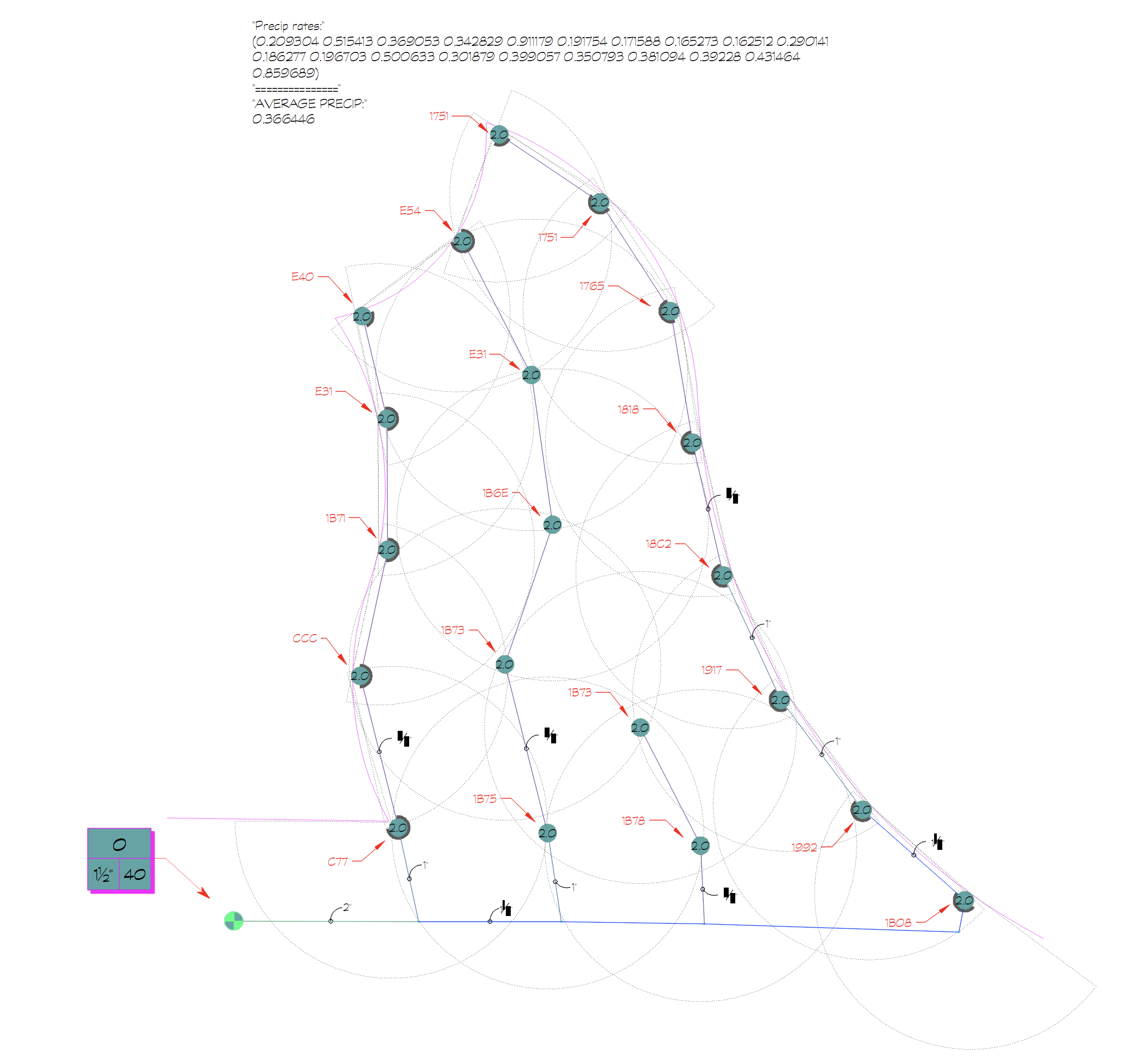
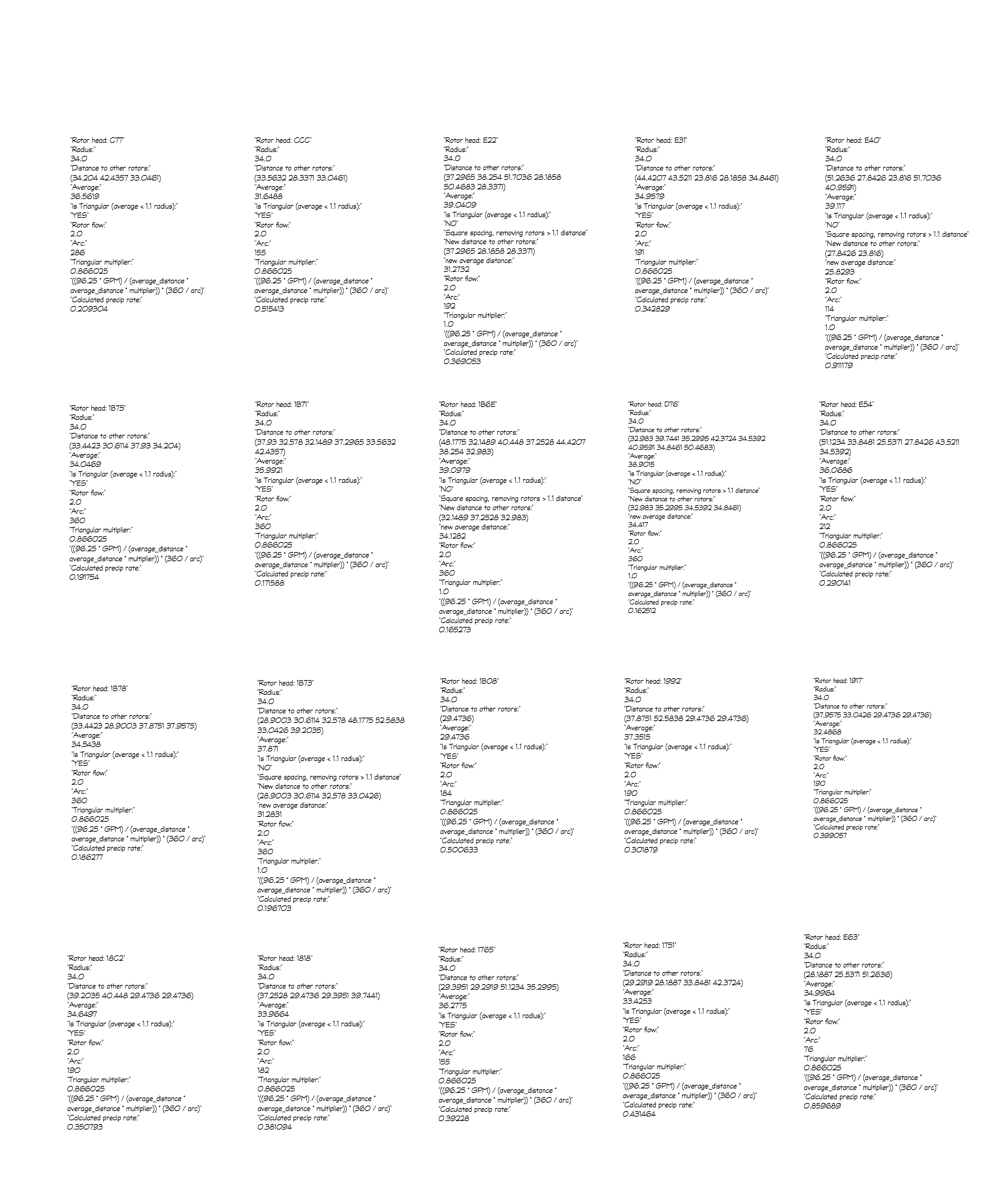
Below is one final example: a zone composed of the same Hunter rotor heads laid out in an irregular pattern.
