System Has No Flow Zones. Please Size the Mainline to Generate Flow Zone (Running a Runtime Schedule)
Issue
When running a Runtime Schedule, you saw the following message when trying to select a station type:
System has no flow zones. Please size the mainline to generate flow zone.

Cause
This issue can occur because:
- You simply need to size your mainline
- You have multiple points of connection (POCs) piped with the same mainline, or separate mainlines and POCs in the same drawing, and the station type you clicked on is not connected to the POC that was active when you attempted to run the Runtime Schedule
- The drawing once had multiple POCs placed in it, but one or more of those POCs were then deleted from the Source Data
Solution
Step 1: Did you size the mainline?
Make sure you've sized your mainline. If not, follow our steps to size the mainline.
Try running a Runtime Schedule again and selecting the same station you originally selected. If you don't get the System has no flow zones message, you've resolved the issue.
Still getting the "System has no flow zones" message? Move on to the next step.
Step 2: Have you placed multiple POCs in your drawing but accidentally removed one or more of them from the Source Data?
Open our Edit Equipment tool, then select one of the POCs in your drawing.
If you see an error finding information on that equipment, the POC you selected may have been removed from the Source Data for your project.
Repeat this step for each POC in your drawing. For each POC that causes the error, delete it from the Source Data, then add it back. Size the mainline again, then try to run another Runtime Schedule.
Still seeing the "System has no flow zones" error when attempting to run a Runtime Schedule? Or can you verify that one or more POCs have not been removed from the source data after being placed in the drawing? In either case, move on to the next step.
Step 3: Further troubleshooting
Run another Runtime Schedule, but this time select the option to Set stations individually (if this option is available).
You should now be able to see which stations go with which POC, making it easy to only click on the stations you need for the specific POC report you are running.
If so, you should be able to assign the appropriate station information accordingly and run your schedule.


But what if the Set stations individually option is grayed out?
If this option is grayed out, it means your drawing includes:
- Valves that are not called out, and/or
- Pipe caps
Check your drawing for the following items:
If your drawing includes valves that need to be called out, label them by placing valve callouts where needed.
Close
Does your drawing include pipe caps? If so, here's what to do:
1. Open our Edit Equipment tool:

F/X Irrigation ribbon, Edit Equipment button

Irrigation Piping toolbar

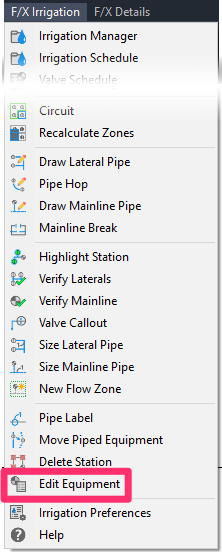
F/X Irrigation menu, Edit Equipment option
or type EquipInfo in the Command line
2. Click a cap in your drawing.


3. Click the thumbnail image of the cap symbol in the Equipment Info dialog box.
4. Select the CAP-PIPE-ID symbol in the dialog box that opens, then click OK.

5. Type ATTSYNC in the Command line and press Enter.

6. Click the existing cap in your drawing. The changes will be applied to the cap symbol, as pictured to the left.
7. Double-click the symbol, and fill out the identifier attribute with the appropriate informormation about the cap.

Close
Step 4: Run another Runtime Schedule.
Once you've accounted for all valves and caps as described in Step 3, run another Runtime Schedule. You should now be able to select the Set stations individually option.


