Divide by Zero Error (Sizing Lateral Pipes, Taking a Flow Total, or Using Highlight Station or Edit Equipment)
Issue
You received an error message containing the text Divide by Zero when either:
- Attempting to size the lateral pipes in your drawing, or
- Running the Flow Total option from within our Circuit tool
- Using Highlight Station and clicking on a zone
- Using the Edit Equipment tool and selecting a drip hatch
Causes/Solutions
The cause and solution of this error will depend on what you were trying to do when you saw the error.
Cause
Your Pipe Data may be inaccurate.
For example, you may be using an incorrect data set of class 200. Even if you are starting a new project, the Pipe Data assigned to the current Preference Set pipe data may be incorrect. If so, you will need to correct this inaccuracy to prevent it from being transferred to any new projects, as well as fix it in the current project.
Solution
Complete the following steps in the exact order listed.
1. Use our Update tool to ensure you have the latest version of our software.
2. Open the Irrigation Manager, and click Pipe Data.


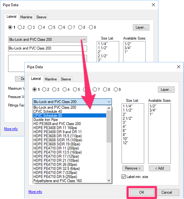
3. The Pipe Data dialog box will open. Use the menu pictured to the left to select a different pipe class from the current one.
Click OK.
Any other pipe class will work. The point is to select a different class from the class you currently have selected for your project.
4. Size the lateral pipe again for the valve that's generating the error.
Is the valve sizing without generating the error? If so, the issue was with the pipe class you previously had selected.
5. Open the Pipe Data dialog box again, and switch back to the original pipe class (in our example, Blu-Lock and PVC PIpe Class 200).
Click OK.

Switching to a different pipe class and then back to the original class will generally correct the Divide by Zero error.
6. Size the lateral pipe again for the same valve. The pipe should size correctly, and you shouldn't see the error.
Still having issues with the laterals not sizing?
Check the Size List in the Pipe Data dialog box and make sure the size list is in the correct numerical order.
In this example, the entry for 20" pipe appears incorrectly at the top of the Size List.
To fix this issue, select the pipe size that's out of order (in this case, 20") and click Remove >.
If necessary, you can then add that size back to the Size List by selecting it in the Available Sizes list and clicking < Add.

Once your pipe sizes are in the correct numerical order, size your laterals and mainline again. Your pipes should now size correctly without generating the error.
7. Still getting the error, or having other issues with your drawing? You may be experiencing drawing corruption. Follow our steps to clean your drawing and all Xrefs.
Close
Cause
You most likely have a drip hatch in your drawing that the system is not recognizing.
Solution
1. Open the Layer Properties panel and follow our steps to:
2. Press the CTRL + A keys (Windows keyboard) or Command + A keys (Mac keyboard) to select all objects in your drawing.
3. While holding down the Shift key, deselect all objects you can see within the intended scope of the design site.
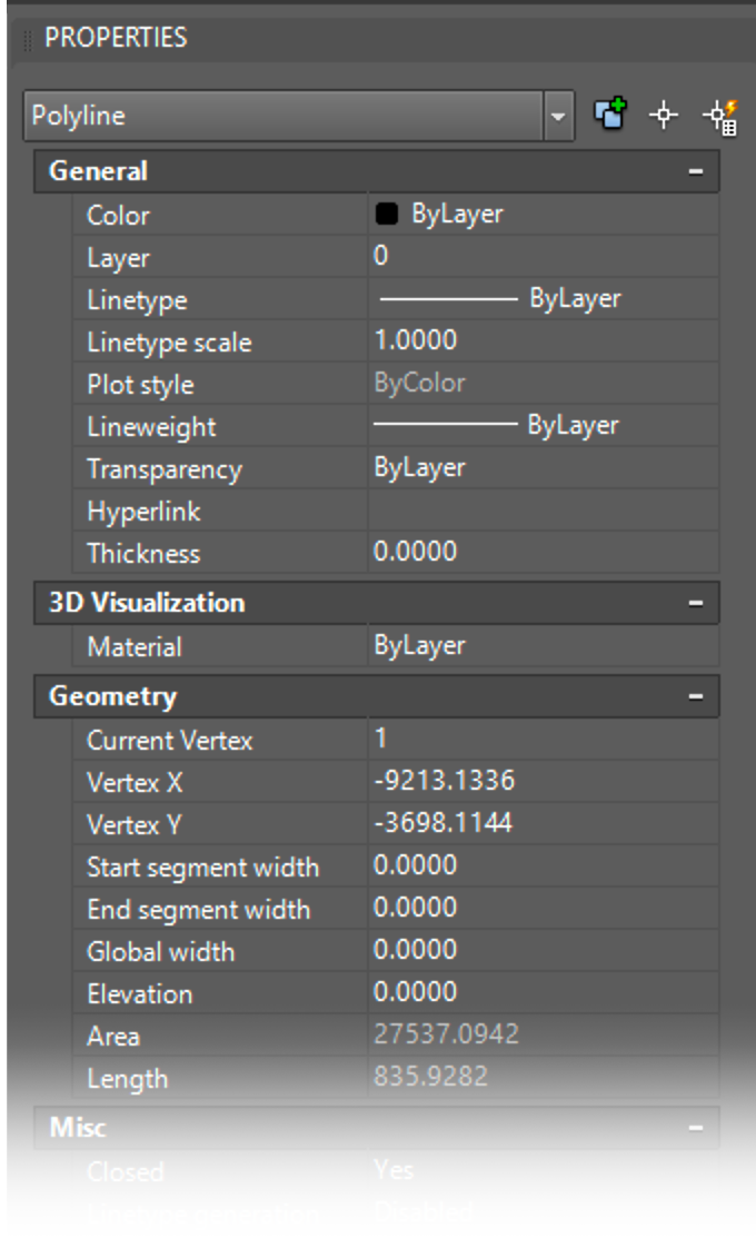
4. Check the Properties panel to see whether anything is still selected.
In this example, a closed polyline well out of the extents of the intended site is still selected.

5. Delete any objects that are still selected.
6. Type PRG in the Command line and press Enter. All deleted items will be purged from the drawing.
You should now be able to use the Flow Total feature without seeing the error.
Close
Cause
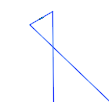
You may have a polyline boundary that is not generating an area.
One common cause is a boundary that intersects itself, as pictured below.


Solution
1 Redraw the problematic polyline area.
2. Type Prop in the Command line and press Enter to open the Properties panel.
Select the boundary and ensure that it shows a valid area in the Area field of the Properties panel.

3. Place dripline within the newly drawn area, and try sizing your laterals again. They should size
Close


