Flow Rate (GPM) Discrepancy Between Size Lateral Pipes Dialog Box and Circuiting or Highlight Station Tool
Issue
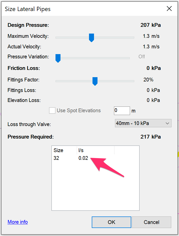
You sized the lateral pipes in your irrigation design and are seeing a flow discrepancy between what you see in the Size Lateral Pipes dialog box and the flow (or GPM) you see when using our Highlight Station or Circuiting tool. Or you may simply not be seeing the full rate you're expecting to see.


Are you trying to colorize your drip zones but they're not coloring correctly? If so, here's what to do.
Cause
Potential cause #1: Improperly piped (and therefore sized) valve
We've seen this issue result from an incorrectly piped valve.
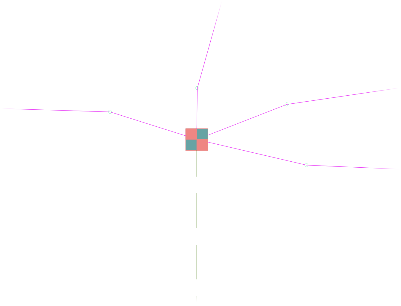
For example, if you connect multiple lateral pipes to a valve, the Size Lateral Pipes dialog box will only display the flow rate/GPM and pipe size information for the last segment processed.
After you click OK, all lateral pipes will be sized correctly, and the valve callout will reflect the correct total flow/GPM.

In this case, the issue is only with the dialog box itself, which is simply unable to display the summarized GPM/Size info of such an improperly piped valve.
Potential cause #2: Pipe transition point overlapping multiple drip areas

Alternatively, your design may include a drip area where a pipe transition point is overlapping other drip areas within the same zone, as pictured in the example to the left.
In this case, the system is looking for any crossing of a transition point within a given area that will allow it to split the flow of an area between all transition points within that area.
If the zone only includes one transition point, as in the example shown below, a slight overlap into another area won't be a factor. In this case, the system will use the insertion point to determine where it should be calculating.


If you have multiple valves in nearby areas, some overlap is not a problem. If you have more than one pipe transition point piped to the valve, the system will look at a crossing, rather than an insertion point, to determine whether an area includes more than one pipe transition point.

Potential cause #3: Incorrectly drawn drip area boundary
We've also seen this issue result from abnormalities in the way a drip boundary is drawn, which will warrant a little investigation.
Solution
Step 1: Verify Laterals
First, use our Verify Laterals tool on your irrigation plan, and address any errors.
Still having an issue with flow rate after addressing any errors detected Verify Laterals? Or is Verify Laterals not detecting any errors? In either case, move on to the next step.
Step 2: Try teeing off
If you're not seeing the full flow rate you think you should be seeing, try only connecting a single lateral segment to the valve, and then tee off from there to multiple locations.
Still having an issue with flow rate? Move on to the next step.
Step 3: Check for and resolve an issue with pipe transition points
Look around your drawing to see whether one or more of your pipe transition points are overlapping two or more drip areas. Make sure that each transition point lands within the desired area without overlap in any other area.


Still having an issue with flow rate? Move on to the next step.
Step 4: Check for improperly drawn drip area boundaries
An issue with how one or more of your drip areas has been drawn can also cause this issue. Follow our steps to check for and correct improperly drawn drip area boundaries in your drawing.
After making the necessary corrections to any drip area boundaries in this way, size your lateral pipes again.
If the calculations still aren't correct, continue investigating your drawing in this way and making any necessary corrections, followed by sizing the laterals again, until the calculations are correct.
Still having an issue with flow rate? Move on to the next step.
Step 5: Redraw the drip zone boundary line.
5A. Delete both the drip area hatch and boundary line.
5B. Draw a new boundary line for the drip area.
Take care not to draw a boundary line with overlapping or incorrect vertices by accidentally snapping to a previously drawn point or another object in your drawing.
5C. Place a new drip area with the new boundary line.
5D. Run our Verify Laterals tool on your drawing again.
5E. Resize the lateral pipes in the drip area using our Size Lateral Pipe tool.


