I Can't Size the Mainline! (Mainline Sizing Troubleshooting)
Issue
You are unable to size the mainline pipe in your irrigation system design.
Causes & Solutions
This is a common issue that is typically caused by an error in your drawing and not by the software itself.
Here are some common examples and solutions:
- Pressure Available at the POC Has Been Exceeded
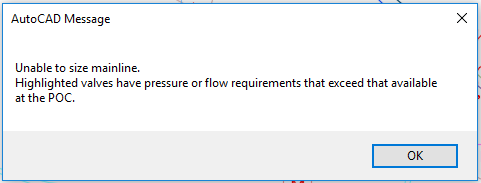
- Unable to size mainline


Getting an error similar to one of the following?
- Pressure available at the POC has been exceeded. Reduce the velocity and try again?
- Unable to size mainline. Highlighted valves have pressure or flow requirements that exceed that available at the POC.
If so, here's the solution.
Close
Seeing an error message similar to the following?
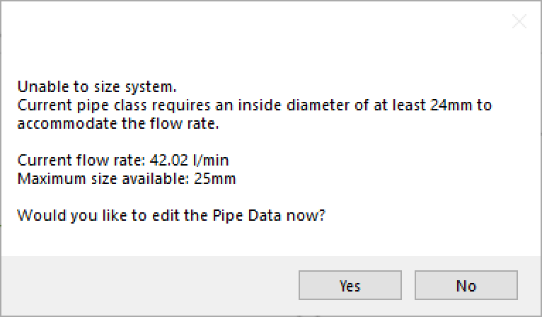
Unable to size system. Current pipe class requires an inside diameter of at least xx to accommodate the flow rate.
If so, here's the solution.

Close
The most common cause of error when trying to size the mainline is when a user copies valves that were already piped. When this happens, both copies of the valve think they are connected to the same pipe. This practice results in a nearly infinite number of mainline loops. So do not copy Valves and Pipes. Instead, place them.
Close
If you've used the EXPLODE command on all the mainline pipe, it reverts the pipes to Line objects. In this case, you'll need to redraw the mainline, and take care to not EXPLODE the pipe or any other smart Land F/X objects.
Close
Sometimes a piping irregularity can occur with the shut-off valve right after the POC. If you use our Highlight Station tool and select the POC, you can see that it highlights only to that valve. And if you select any mainline downstream of the Master Valve, it will highlight everything, but only back to that shut-off valve – not the POC.
To fix this issue, you can just delete the mainline pipe segments between the POC and the master valve, and then repipe them.
Close
If you have a booster pump in your system, use our Edit Equipment tool to select the pipe segment that includes the booster pump. If you see that this segment is still unsized, it means that the software is not recognizing that segment as it sizes this system. This issue would suggest a piping error – most likely a segment of pipe that is not connected.
In this case, you'll need to delete a segment of pipe so the system is not looped, and then use our Highlight Station tool to see what is still connected. In this fashion, you can determine which pipe segments need to be redrawn.
Close
The system can only deal with one water source at a time. If you intend to have multiple meters running at the same time, you'll need to create a Custom POC that includes the demands of the two combined meters, and then size the mainline using that POC.
For information and instructions on using more than one source or POC in your design, see our documentation on using multiple water sources.
Close
If you're experiencing this issue, see our Sizing Mainline: Drawing Freezes During "Recursing Pipe" article.
Close
You may be simply seeing required pressure rates for your valves (or drip valves) that are much too high for the rate you've set for the service line.
For example, let's say you've set the service line to 65 PSI and are proposing 25 PSI drip assemblies, and you're somehow losing 18.92 PSI though the valve. But then, when you hand clculate, it appears that you should have 33.79 PSI at the mainline before the valve, then lose lose 3 PSI through the valve (putting you at a bit over 30 PSI), and then the regulator on the assembly drops the pressure to 25 and the system should work just fine. So what's the deal?
In this case, the valve loss is due to the amount of flow you've set to that valve. To verify, look at the charts for that exact valve model and you'll see the required inlet pressure to run at the given reduced pressure. That difference is considered the valve loss.
If you're losing that much pressure, it's because the design of that particular equipment results in that pressure difference.
Your options in this case include:
- Selecting a different manufacturer's valve to use in this project
- If it's a drip valve, you can also choose to put a regular valve in its place and note the need of a filter or pressure regulator in conjunction with the standard valve.
We understand the potential frustration in wanting (or being required) to use a particular valve, or manufacturer, only to find that the valve in question comes with this level of potential pressure difference. Unfortunately, it's an issue that's tied to the design of that particular valve – not to the software. It's also one of the conditions for using pressure regulation equipment.
Want to learn more about pressure regulation and the necessary equipment, see our Understanding pressure regulation webinar, presented by Kelsey Jacquard of Hunter Industries.
Close
If a looped mainline is not sizing correctly at half the flow, the cause is almost always the same: A piping error is preventing your "loop" from actually being connected all the way around. As a result, it's not actually a loop.
To resolve this issue, first delete a section of pipe, then use our Highlight Station tool to locate the break in the pipe. You can then re-pipe the broken section(s), plus the section you deleted.
Close


