Customize Valve Callouts
Quick video
- The Irrigation Valve Callout Source Block Drawings
- Editing Our Existing Callout Styles
- Adding New Callouts
- Creating a Schedule Symbol
- Related Webinars
Like other callouts, valve callouts are placed as blocks. You can customize our valve callout blocks to meet your standards.
You can also create your own valve callouts and save them into our system using our Save Block tool.
Looking for instructions for placing valve callouts in your drawings? See our Valve Callouts page.
Attention: Do you have customized valve callout styles?
We've changed our valve callout styles as of April 2018, adding an attribute for the size of the valve, as well as a background mask set to Color 133. You may need to re-create any custom valve callout styles you've made in order to accommodate the new attribute and the background mask (if you want it in a different color, for example). The good news is that you'll only have two source files to maintain for each custom style: one for the right callout and one for the left. (Previously, you had to maintain separate right and left source files for each valve size.) Read on for details and instructions.
The Irrigation Valve Callout Source Block Drawings
The irrigation valve callout source block files are located in the folder LandFX/Blocks/Graphics/Irrigation/Callouts. Their filenames start with LAFX-VALVECO.
We have 5 basic callout styles for Imperial units:
- LAFX-VALVECO
- LAFX-VALVECO2
- LAFX-VALVECO3
- LAFX-VALVECO4
- LAFX-VALVECO5
You'll see a Right (R) and Left (L) version for each of these styles. When editing a style, don't forget to edit both the R and L versions.
As with our other cloud-based blocks, you won't see these source files in this location until you've placed valve callouts in a drawing for the first time. Once you've placed a callout in a particular style, the source files for that style will download to this location automatically, and you'll be able to edit them.
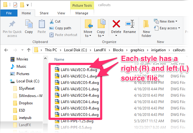
Note that we've changed our valve callout styles as of April 2018, adding an attribute for valve size. This new attribute made it unnecessary to have a separate source file for each valve size. We now only have only 10 total default callout styles (5 styles for Imperial units, and 5 similar styles for metric).
Because each of these source blocks includes an attribute for the valve size, we no longer need a different source file for each valve size.
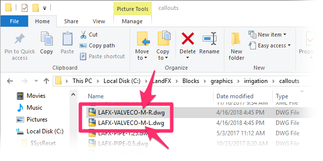
The Metric styles are named and numbered similarly to their Imperial counterparts, except the file names will include the marker -M- for metric. You'll see an R and L version of each metric style as well.
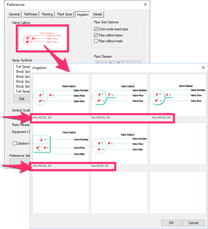
These 5 callout styles correspond with the callout styles that are available from the Irrigation Preferences.
Note that the name of each of these styles matches the name of that style's source drawing. So if you've made edits to the style VALVECO2, you'll select the callout style of the same name here, and that style will appear in your drawings when you place valve callouts.
Editing Our Default Valve Callout Styles
We recommend using our default valve callout styles as templates for creating your customized valve callout styles rather than creating your custom callout blocks from scratch.
Open any of the valve callout source block files and make your desired changes. You can then choose to either overwrite the existing callout style or save your own customized callout style with a new file name, leaving the original style intact.
Remember: If you've already created custom valve callouts prior to April 2018, you'll need to create them again to accommodate the size attribute. It won't take long – you'll only need to edit the L and R versions of each callout style you use. And that's it!
Note that the LandFX/Blocks/Graphics/Irrigation/Callouts folder contains three files for each valve callout block:
- A DWG file (.dwg) file (the actual callout block drawing)
- An AutoCAD slide (.sld) file (the thumbnail slide for the callout)
- An XML (.xml) (allows the system to read the block and slide files)
Open the DWG source file for both the Left (L) and Right (R) versions of the callout you want to edit.
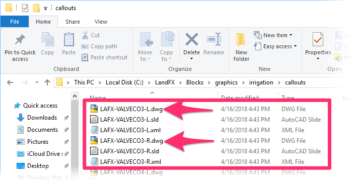
You can then make your changes to that callout style.
To overwrite the existing callout style, just save the source file once you've made your changes. To create a whole new callout style of your own but keep the default style intact, use our Save Block tool and save your custom callout style with a new name.
Once you've made your edits, you'll need to create a schedule symbol for your custom callout style in order to see and select it in the Irrigation Preferences, as well as to include that symbol in your Irrigation Schedules.
Editing Attribute Text
All callout styles contain attributes, which you can edit and move around to your liking. An attribute is a chunk of dynamic text that allows "smart" blocks (such as valve callouts) to take on different values each time they're inserted into a drawing.
We've built several attributes into our default valve callouts.
Our default valve callout source blocks include three attributes:
- Valve Flow (GPM)
- Valve Number
- Valve Size
Important: If you use Imperial units, make sure you use a multi-line attribute for the Size attribute and do not give it a default value. This will accommodate fractions. If you use Metric units, you only need to create an attribute called Size – no need for multiple lines.

We've also created several additional attributes you can use in your custom valve callouts. Here's a list of all possible attributes you can include in your customized valve callout style:
Tag
Result
NUM
Valve number
VALVE
Valve number
X00
Valve number
XX
Valve number
SIZE
Valve size
0.0
Valve GPM
GPM
Valve GPM
TYPE
Valve type (turf spray, shrub rotor, etc.)
PSI
Design pressure
DESIGNPSI
Design pressure
BARS
Design pressure
PRESSURE
Design pressure
PRECIP
Precip rate
HEADS
Number of heads tied to the valve
For more information on these attributes, including how to edit and move them, see our Attribute Definitions for Valve Callouts documentation.
Insertion Points
Each callout style will need to have left (L) and right (R), versions, depending on which direction the callout needs to extend from a valve when placed in a drawing.
The L labels have their insertion point at the farthest right end point of the label line. The R labels have their insertion point at the farthest left end point of the label line. Keep these insertion points in mind when you make your edits.
Background Mask Color
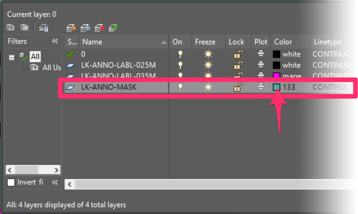
Valve callouts now include a background mask, which comes in at color 133 in our default callouts. To change the mask color, just change the layer color of the mask in the source file. It will be on the layer LK-ANNO-MASK. If you change the mask color, take care to change it to a color that contrasts well with your label text color.
Adding New Callouts
If you want to add new callouts, we recommend maintaining the default naming convention by adding to the number or replacing an existing label entirely but retaining the old name. You'll then use our Save Block tool to save the new block.
In creating customized valve callouts, you only need to use Save Block if you want to:
- Save an edited version of one of our callout styles but leave the original style intact, or
- Create your own valve callout style from scratch.
If you want to edit and overwrite one of our existing callout styles, you can just edit the source file for that callout.
The easiest method for creating a new label type is to open an existing label that closely matches your layout goal. All text is an attribute, so don’t change it. Instead, change the font style or physical size of the font to meet your preferences or office standards.
Want to add or edit attributes? See our Attribute Definitions for Valve Callouts page.

Note that the LandFX/Blocks/Graphics/Irrigation/Callouts folder contains three files for each callout block:
- A DWG file (.dwg) file (the actual callout block drawing)
- An AutoCAD slide (.sld) file (the thumbnail slide for the callout)
- An XML (.xml) (allows the system to read the block and slide files)
Open the DWG source file for both the Left (L) and Right (R) versions of the callout you want to edit.
Make the necessary changes, then use our Save Block tool to save the new block.
When you save the block, don't forget to follow the block naming conventions described above.
Creating a Schedule Symbol
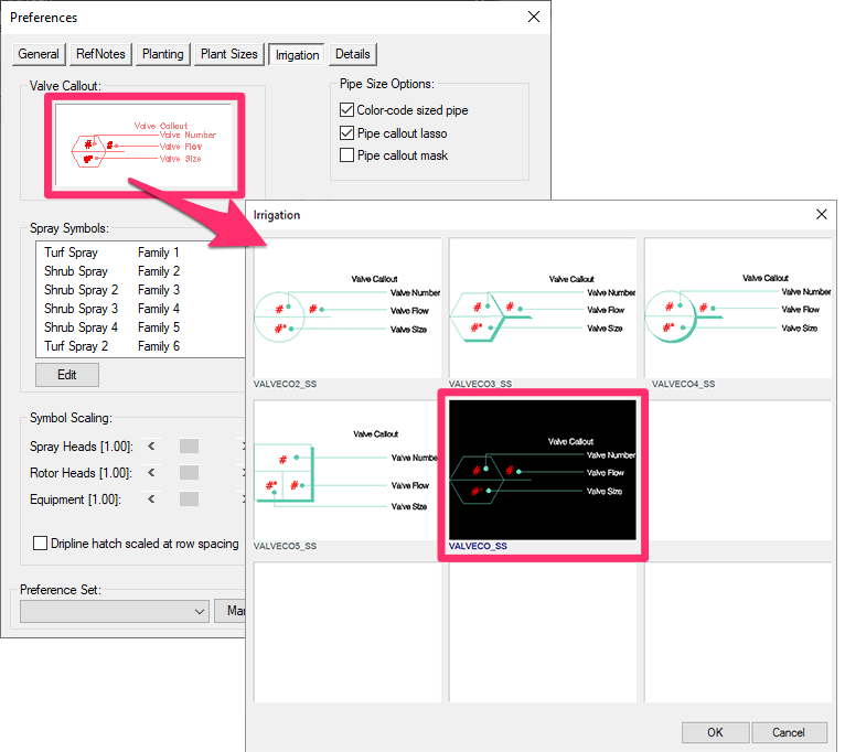
If you add a Valve Callout, or revise an existing one, the new callout will also require you to create a schedule symbol. This symbol will appear in the Irrigation Schedule, showing aspects of the callout such as the locations of the valve number, valve size, and flow.
You'll also need to create a schedule symbol in order to see and select your customized valve callout in the Irrigation Preferences, as pictured below.
Here's how to create a schedule symbol:
1. Go to the folder LandFX\Blocks\Graphics\Irrigation\schedule_symbols.

2. From this folder, open one of the Schedule Block files used to represent the valve callouts in the Irrigation Schedule.
These files are named according to the following format: LAFX-VALVECO(number)_SS.dwg. For example, the file LAFX-VALVECO1_SS.dwg contains the Schedule Symbol for Valve Callout 1.
Each of these blocks includes an appropriate insertion point for the schedule, as well as labeled descriptions of the locations of the Valve Number, Valve Flow, and Valve Size.
3. Bring in your revised valve callout, and replace the existing one.
4. (only necessary if you've created your own callout style) Using the Save Block tool, save this new drawing into the Schedule_Symbols folder, named LAFX-VALVECO(number)_SS to match the number of the valve callout it represents.
Skip this step if you are customizing and overwriting one of our default callout styles.
5. You'll then create a thumbnail slide for your valve callout.
If Save Block does not create an acceptable slide automatically, of if you need to reshoot the thumbnail slide for any reason, use our Best Practices for Creating the Thumbnail Slide to create a slide manually.
Related Webinars
- Irrigation Customization: We cover the Irrigation Preferences, including what to consider as you’re setting up your office standards, and what will and won’t change on the fly when you modify these settings, as well as customizing irrigation symbols. (1 hr 2 min)
- Dotting Your Irrigation I's: Each client will have different styles and requirements, but the concept is the same: You should feel comfortable matching any client’s standards. We'll show you how. (1 hr 1 min)
- Working With Blocks: Take a broad look into the role of blocks within Land F/X and how to integrate your personal set of blocks into our system. (1 hour 4 min)
- Customizing Irrigation – What You Need to Know: Join us for a discussion on the "need-to-knows" of making the software work with your office standards. We'll show you the different ways you can customize, and you'll pick up some valuable tips for setting up the software to meet your office standards. (1 hr 1 min)


