Initial Mainline, Service, and Water Source Layout
- Establishing a Point Of Connection (POC)
- Placing a Water Source and Backflow
- Placing Quick Couplers or Hose Bibbs
- Schematic Mainline Layout
- Place Remote Control Valves
- Mainline Pipe Information
- Related Webinars
An initial mainline and service layout provides the first sketch of the irrigation layout, allowing you to adjust it as you develop the lateral system.
Though this initial layout is optional, we recommend developing an understanding of where the mainline will be running. This knowledge will provide the basis for the intelligent placement of control valves for the lateral system.
Creating the initial layout will require you to place irrigation equipment into your drawing. Before you can place a piece of equipment in your drawing, you will need to add it to your project using the Irrigation Manager. For more information, visit our Irrigation Manager documentation section.
Establishing a Point of Connection (POC)
If you haven't yet done so, review the Source Data to determine the type and size of the source, as well as the Pipe Data to select which types of pipes you will use in the design.
When you select a water source from the Source Data, you'll establish one or more POCs and determine the source flow and pressure available to your project. The system will automatically provide you with a symbol for the source, allowing you to place it in your drawing.
Place the Water Source and Backflow
Before you can place your water source in your drawing, select a water meter or POC using our Source Data tool.
You can place your water source with the Place Equipment tool by following the steps below, or place it directly from the Source Data.
Placing a Water Source or Point of Connection (POC)
In this example, we'll assume your POC is a 1-inch water meter.
To place the water meter, open our Place Equipment tool:
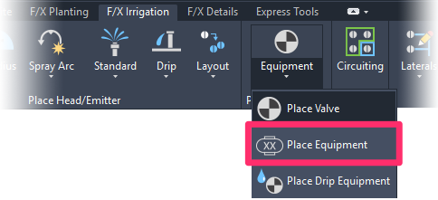
F/X Irrigation ribbon, Place Equipment flyout
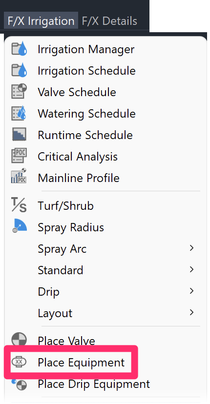
F/X Irrigation menu, Place Equipment option
or type FX_PlaceEquip in the Command line
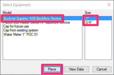
You'll now see the Select Equipment dialog box, which lists all auxiliary equipment that has been added to the project.

The water meter that was added to the project is a 1-inch water meter, and was added for POC 01. Highlight the water meter and click Place to place it in your drawing.

The text defaults to M, but you can enter any letter or number you wish. Typically, if your project contains only one meter, just let the default apply. The next meter you add will automatically be labeled M2.
Placing a Backflow Device
Select the Place Equipment tool again to place a backflow device.
In the Select Equipment dialog box, click the name of the backflow device to highlight it.
All sizes offered by the manufacturer for the selected model will now be available for input. Select the size of backflow that makes most sense for the project, then click Place to place it in your drawing.
If you need to know the manufacturer's performance data to make a decision on the most appropriately sized backflow device, click View Data to view the manufacturer's data.
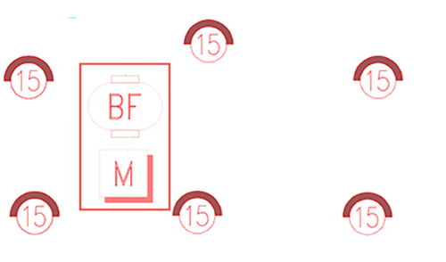
Here's an example of a backflow device placed in a drawing just off the water meter.
Placing a backflow device is optional at this time. The intent is to locate the source so you can begin laying out where your mainline will occur, and you will start at your water source.
Backflow devices protect the public water supply from any pollution that may result from your project. Try to place the backflow device as close as possible to your source. Some agencies indicate that it can be no farther than 10 feet (3 meters) from the water meter or source, so check with the agency if you are not sure.
Place Quick Couplers or Hose Bibbs
Quick video
Quick couplers or hose bibbs allow a hose to be hooked to the irrigation supply for manual watering.
We recommend placing the locations of these items early on, as the mainline will need to run to them.
To place a quick coupler, for example, open the Place Valve tool:
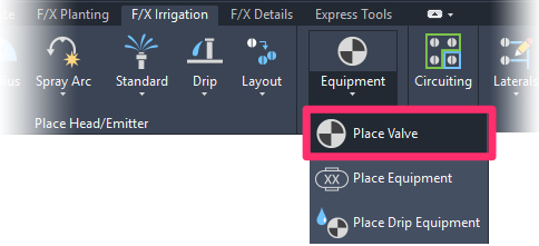
F/X Irrigation ribbon, Place Valve flyout
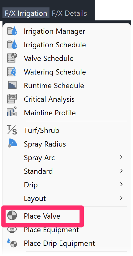
F/X Irrigation menu, Place Valve option
or type FX_PlaceValve in the Command line
The Select Valve dialog box will list all valves that have been added to your project.
Highlight the valve you'd like to place in your drawing (example: a quick coupler valve).
Click Place to place the valve.


A target for the quick coupler (or hose bibb) will appear at the CAD crosshairs (see image below), and will consist of three radius indications. The radii correlate to hose lengths, and include a 50-, 75-, and 100-foot radius (15, 22, or 30 meters).
These measurements relate to possible hose lengths, and you can use them to help determine the location of the quick coupler.
Click to place quick couplers around the site at your desired locations.
Schematic Mainline Layout
The drawing of a schematic mainline layout is an optional but recommended phase. This layout may evolve as you continue to define where valves are located.
As soon as you place a POC into your drawing, the system automatically creates a non-plot layer named LI-PIPE-MAIN-NPLT. Because it's non-plot, this layer won't be visible when you print or plot your design – even if you leave it on accidentally. With this layer as the active layer, draw the initial layout of the mainline. This layout should most likely start at the POC and connect to the various quick couplers (or hose bibbs) you have placed in the drawing. It should also reflect your initial plan for the mainline layout. You'll adjust the schematic layout as you add valves and, possibly, move objects around.
The layer mentioned above will become active as soon as you place your POC. Just use standard line draw commands (Polyline, Line, etc.) in CAD to draw what you think is a logical layout for your mainline. You'll most likely revise this layout during the process of drawing your lateral pipe, as the mainline is often graphical in nature and is shifted or adjusted to avoid conflicting with the graphics of the lateral system, as well as to respond to mainline needs such as valve locations.
Place Remote Control Valves
You can place a valve for a circuit zone of heads at any time during the piping process. With the mainline laid out in a schematic process, and with the lateral systems zoned into groups, it's often best to place the valves in logical locations before lateral piping so you know where the lateral piping is connecting.
Select the Place Valve tool again, as described above.
Select an appropriate valve size for the flow of the circuit zone.
Click Place to place the valve.

Note that when you highlight the valve on the left, the size options will be visible on the right for selection.
To help you decide the most appropriate valve size for the flow of the circuit, click View Data while the valve is highlighted. The valve's official manufacturer data will appear in your Web browser. From here, navigate to the manufacturer's performance data for this valve, and review the information for related flows, pressure loss, and appropriate size valves for a given flow. The performance data is also helpful in determining the maximum flow and pressure loss a valve should have. A maximum pressure loss of less than 10% of the static pressure, or between 5 and 6 psi (0.75 to 0.9 kPa), is a normal practice.
Place the size of remote control valve that best fits the requirements of each zoned lateral system.
As you place valves and adjust their locations, you may need to adjust the initial mainline layout in its location.
Mainline Pipe Information
For general information about mainline pipe, see our Mainline Pipe article.
Related Webinars
- Irrigation for Beginners: We'll show how to navigate through the Irrigation ribbon and build a familiarity with our conceptual-level tools. You'll also learn the basics of adding equipment to a project, placing, piping, sizing, and scheduling. (1 hr 45 min)
- Irrigation Tools – What You Need to Know: We'll show you the ins and outs of basic irrigation setup using our software. You'll also learn the essentials of placing equipment such as drip, sprays, and rotors. (1 hr 6 min)
- Irrigation Tips & Tricks: We'll show you some advanced tools you may or may not know about. You'll also learn techniques and best practices that will help speed up your workflow. (1 hr 3 min)
- Existing Irrigation: Learn the techniques, tools, and tricks you'll need to expand an existing system, including how to use a pipe cap to account for existing flow and add new valves to an existing mainline. (56 min)
- Advanced Irrigation Troubleshooting: Learn to think like a Land F/X irrigation troubleshooter. We'll show you why your symbols don't match, why you would see the message "Error accessing equipment data" (and how to fix these issues, as well as tips on pressure losses and precip rates, pipe caps, system monitors, and flow zones. (1 hr 3 min)


