
Rooftop and Multiple-Story Irrigation
Updated on: January 19, 2024
Quick video

One of the major challenges presented by multi-story or rooftop designs lies in the balance you need to strike between showing the design graphically and accounting for pressure loss caused by elevation change.
Although you have several options for setting up your drawings for this type of system design, we recommend keeping each floor in its own DWG file. Read on for our recommended method for multi-story irrigation design. Separating the floors into their own DWG files provides a simple but effective way to keep track of each level of irrigation in your design.
Each foot in elevation results in a loss of .433 PSI of water pressure, which directly affects water in pipes placed at that elevation. For example, if you place the second level of your design at 10 feet above the first level, you'll lose 4.33 PSI of water pressure at the second level.
Step 1: Set up your drawing files
First, Xref each floor's base file into the corresponding irrigation plan.


Assign the same Land F/X project to each DWG to ensure you're using the same equipment throughout the site.
After you've finished the design for each floor, call out and size your laterals in the file for each level of your design.

Step 2: Set up your points of connection (POCs) for each floor or level
Open the Irrigation Manager, then click Source Data to open our Source Data tool.


Create a custom point of connection (POC) for each level of your design, making sure the available flow and pressure for each POC is zeroed out.
This step will allow you to size each level's mainline and obtain an accurate account of the demands for that floor.
Place each POC in the corresponding DWG file for that level.


Step 3: Draw and size your mainline pipe
Open our Mainline Pipe tool:
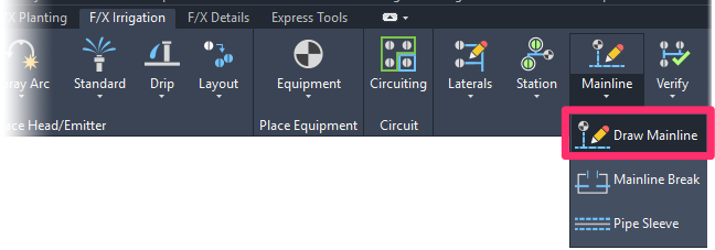
F/X Irrigation ribbon, Draw Mainline flyout
or type MainlinePipe in the Command line
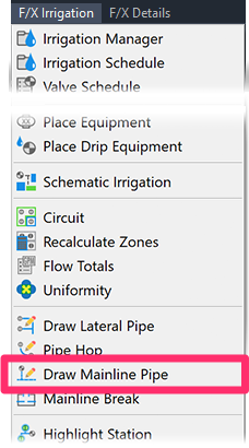
F/X Irrigation menu, Draw Mainline Pipe option

Connect each POC to the rest of the irrigation design with mainline.
Size the mainline in the file for each level or floor in your design.
When sizing the mainline with 0 flow and pressure, you'll see a message stating that you have a design that has exceeded what you have available. Don't worry about this message for now – just click No.


You'll see a Critical Analysis each time you size the mainline for a POC. Take note of the required pressure and flow for that POC – you'll need those numbers later.
Step 4: Account for your system's elevation demands
To obtain the accurate elevation demands of the overall system, start a new drawing and create a new POC.
This POC will be your true representation of what you have available for the site, so make sure the Residual Flow Available and Residual Pressure Available reflect what you have available.


Place this POC at the elevation where your main connection will be.
p
By drawing in an elevation view, you can now account for the friction loss due to the elevation runs to each floor.
Add a pipe cap to the Irrigation Manager.


Edit the cap, and select the symbol that has an ID attribute.
Place this cap at the proper elevation of each floor.
For each cap, enter the demands you noted when sizing each floor's POC.


When finished placing caps, pipe your mainline from the POC to each cap.
Open our Spot Elevation tool:
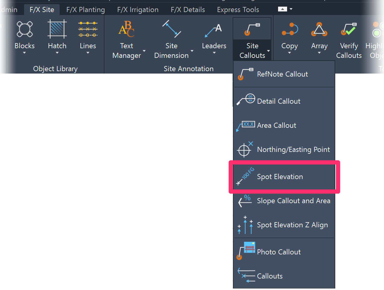
F/X Site ribbon, Spot Elevation flyout
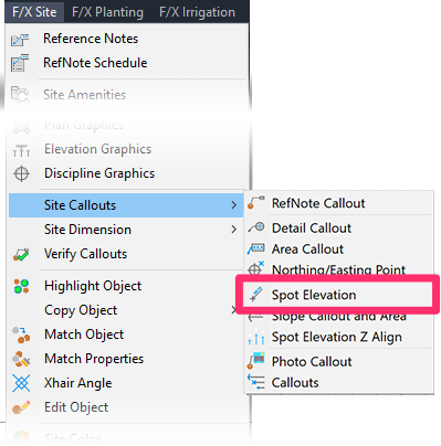
F/X Site menu, Spot Elevation option
or type FX_PlaceSpotElevation in the Command line
Place a Spot Elevation callout next to the POC and each cap with the proper elevation values.


Size your mainline, ensuring that the option to Use Spot Elevations is selected.
You'll now see your final Critical Analysis of how the system is going to perform.

You can run a Valve Schedule to see the breakdown of each cap and the required pressures for each level.
