Change Insertion Points of Plant Labels
Quick video
- Insertion Point Defined
- When Do I Need to Think About Insertion Points?
- How to Test and Fix the Insertion Point
- Related Webinars
If you choose to use our default callout styles, you won't have to worry about insertion points because we've already set them up for you.
If, however, you decide to edit the default callout styles to meet your office standards, that's when you'll have to start thinking about insertion points.
Note that this issue can apply to various aspects of callout placement, including leader position and font justification.
Having an issue with labeling in a drawing that's rotated in a DVIEW twist? Follow our steps to remove a DVIEW twist from a drawing.
We updated our default plant labels in March 2019, adding styles that use MLeaders and improving the block-based label styles. You may not have these updated label styles. To access these styles, you'll need to delete all existing default plant label blocks and slides. For instructions, see our Updated Plant Labels documentation.
Insertion Point Defined
The insertion point of a callout is the location where the leader meets the callout box when you place that callout in your drawing.
If overlooked, this extremely important detail can cause any number of issues in your drawing. With plant labels, the location of the insertion point will depend on whether you are using an MLeader or block label style.
Block Label Styles Insertion Points
Each of our block-based label styles has a left and a right version, depending on whether you place a label to the left or right of a plant.
With block labels, the insertion point is the point at the edge of the callout box where it meets the leader. The left callout's insertion point will be on the right edge of the callout box, and the right version's will be on the left.

If you were to open the source files for the left and right label of one of our block plant labels, the insertion points of each would be as shown below.

MLeader Label Styles Insertion Points
With our MLeader labels, the insertion point is the exact center of the callout box.

MLeaders will only stop at a line-based object – a line, polyline, tiny circle, etc. If the insertion point does not have one of these items, the leader will continue through the insertion point and extend incorrectly into the callout.
Rather than having right and left versions, each MLeader callout style only has one source file. When you open the source file for an MLeader callout style, the insertion point will also be in the center of the callout.
When Do I Need to Think About Insertion Points?
The potential issue arises when you want to make changes to one of our default callout blocks – or one of your own. A callout's insertion point should always be at the coordinates 0,0. If you make changes to the positioning of the callout components, you'll need to make sure you've maintained the integrity of the callout's insertion point.
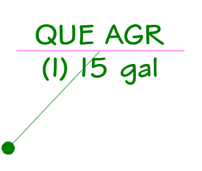
Here's an example of a block-style label that a user edited without maintaining the correct insertion point and subsequently placed in a drawing:
Note that the leader is extending from near the middle of the label, rather than the end.
How to Test and Fix the Insertion Point
To correct a callout's insertion point, you'll simply open the drawing containing the callout block and reset the insertion point to 0,0.
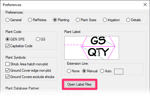
You can access our callout block files directly from the Planting Preferences.
Click the Open Label Files button.
A series of DWG files will open. Each of these drawings is the source file for one of the label types you've placed in the current drawing. Find and open the source file you need to correct.
Of course, you can also navigate to the folder LandFX/Blocks/Graphics/Callouts, or to the folder where you store you callout blocks, and open the block drawing from there.
Setting the Insertion Point
With your callout block drawing open, type INSBASE in the Command line.
The Command line will prompt you to: Enter new value for Insbase, followed by a series of numbers in brackets. These numbers show the coordinates of the callout's insertion point.
If these numbers are anything other than 0, (or 0.00, 0.000, etc., depending on your settings), you'll need to set the coordinates to 0. Simply type 0,0 in the Command line.
Testing the Insertion Point and Adjusting the Callout
In the case of the errant callout block in our example, we can be sure that the leader is coming in at the wrong location because the callout block is placed incorrectly in relation to its insertion point.
Here is our problematic plant label again, with the leader extending from the wrong location:

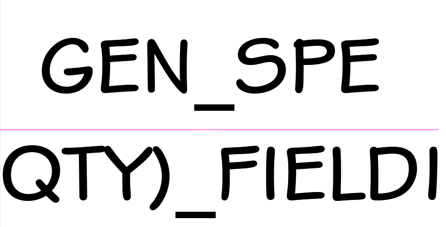
The image to the left shows what the source file of our callout looks like when we open it.
At first glance, it's difficult to tell where the insertion point is.
We can now perform a visual test to show where the callout is currently sitting in relation to the insertion point. Type LINE or PLINE in the Command line. The Command line will now prompt you to: Specify start point.
Type 0,0, then press Enter.
A line (or polyline) will appear in your drawing, originating from the point 0,0.
In this example, we can see that 0,0 – the origin of the line – is the exact location from which the leader extended in the drawing, as pictured above. That means that the insertion point is correctly set to 0,0, but the callout has been moved to an incorrect location in relation to that insertion point.
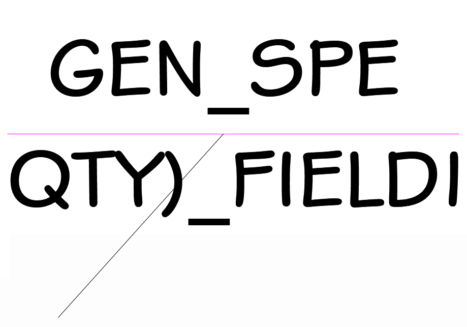
At this point, all we need to do is move the callout to a point where the line – and future leaders – will extend from the correct location.
The image to the left shows the corrected label.
Delete the line you drew, then close the label source file and save your changes.
Back in your planting plan, type REDEFINEBLOCK in the Command line and press Enter.
Click a label in the drawing. It should reflect the changes.
Related Webinars
- Planting F/X Setup: If you're trying to make Planting F/X work with your firm's existing style standards, this webinar is for you. (58 min)


