Drip Emitter Troubleshooting – Drip Area is Showing 0 GPM (0 Flow), Flow Rates are Inconsistent or Incorrect
Issue
You're having an issue with flow rate calculation in one or more drip areas (Area for Drip Emitters, Drip Spray, or Dripline) in your drawing. Your drip area(s) may be showing incorrect, inconsistent, or even zero flow.
One or more of your drip areas may be unable to read some or all of the plants in an attached Xref. You may also have tried calculating your flow rates manually (and verified that those calculations are indeed correct) and your manual calculations didn't match the flow rates you're seeing in your drawing.
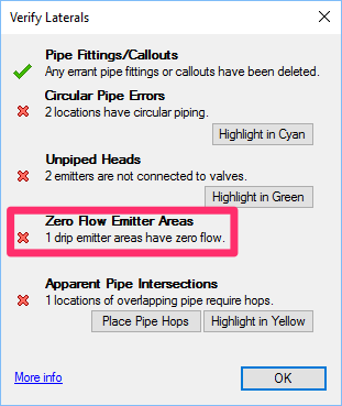
You may have used our Verify Laterals tool on your plan and found that one or more drip areas have zero flow.
This issue can often result from drawing corruption. To prevent issues like this one, you should always be completing our drawing cleanup steps on your irrigation plan and all Xrefs.
Quick video
Cause
Drip area functionality is the single most involved and error-prone Land F/X feature, with a large number of potential fail points. As a result, troubleshooting it can be time consuming and will require you to be patient and meticulous while going through every step as necessary to discover and address your specific issue.
For this feature to work correctly, several key factors must be in place, including:
- Plants need to be in either the irrigation plan or a single Xref – not both.
- The Xref containing your planting plan needs to be:
- Free of errors, and
- Inserted correctly so it lines up with the irrigation plan
- The plants' container sizes need to match up with the emitter assignments.
- The bounding polyline for the emitter area needs to be free of errors.
- Only project plants are being used in the drip emitter areas – no Concept Plants.
Solution
Is this your first time troubleshooting a drip area? Do this first.
The following quick test will help you familiarize yourself with how drip areas should work:
1. In a blank drawing, assign the project and scale. Place a single shrub near 0,0. Save this drawing as the planting plan.
2. In a different blank drawing, assign the same Land F/X project and scale. Then use our fxREF tool to attach the planting plan you created in the previous step.
3. Add the drip emitter area to the project, then assign one of those emitters to the container size of the single shrub in the planting plan.
4. Place the drip emitter area as a simple rectangle around the shrub.
5. Edit the drip emitter area, and confirm that it has a flow.
Now that you've seen how this feature should work correctly, it's time to dig deeper to find and correct the problem.
Step 1: Check for plants in the irrigation plan.
If you have plants in your irrigation plan, the system will abort looking for plants in the Xref – a necessity in preventing the huge processing time burden that processing an Xref for plants can impose upon simpler plans.
While you may be operating under the assumption that the irrigation plan does not include plants, please note that this issue is the most common cause of the drip area feature misfiring, so it's crucial that you check for plants using the following method.
Here's a simple way to check for plants in the irrigation plan:
With the irrigation plan open, place a Plant Schedule with the Include Xrefs option unchecked.
If the schedule generates with plants, you've found the issue. Locate and delete the plants that are appearing in the schedule.
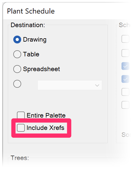
Important considerations:
• Use Zoom to Extents to look for plants in your drawing.
It's crucial to zoom your drawing to its extents to rule out any plants placed away from your irrigation system. Any plants floating around in your drawing will throw the Drip Emitter Areas off.
More information on Zooming to Extents
• Make sure to thaw and/or turn on all layers in your drawing before generating a Plant Schedule.
Any plants that are on layer that is frozen or turned off will not display in a Plant Schedule but will still cause issues with your drip emitter flows.
Step 2: Check for issues with the planting plan Xref.
2A. Open the drawing containing the planting plan. Type AUDIT and press Enter.
2B. Type UCS in the Command line and press Enter. Then type W to set your drawing to World.
2C. Type INSBASE in the Command line and press Enter. If anything other than 0,0 appears:
- Detach the Xref of the planting plan.
- Then use our fxREF tool to re-insert the planting plan as an Xref. fxREF will cross-check to ensure the Xref is inserted correctly at 0,0.
2D. In the planting plan drawing, open our Project List tool and confirm that the planting plan is set to the same Land F/X project as the irrigation plan.
2E. Place a Plant Schedule with the Include Xrefs option unchecked, and confirm that:
- The plants are appearing in the schedule, and
- The size of the plant in the schedule matches up with the emitter assignment for that size shown when you edit the emitter and click Emitters (see images below)

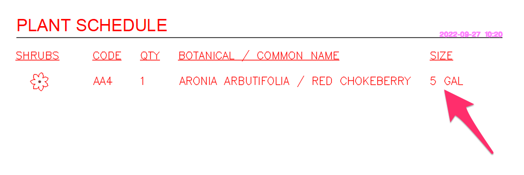
Plant size shown in the Plant Schedule (example: 5 GAL)
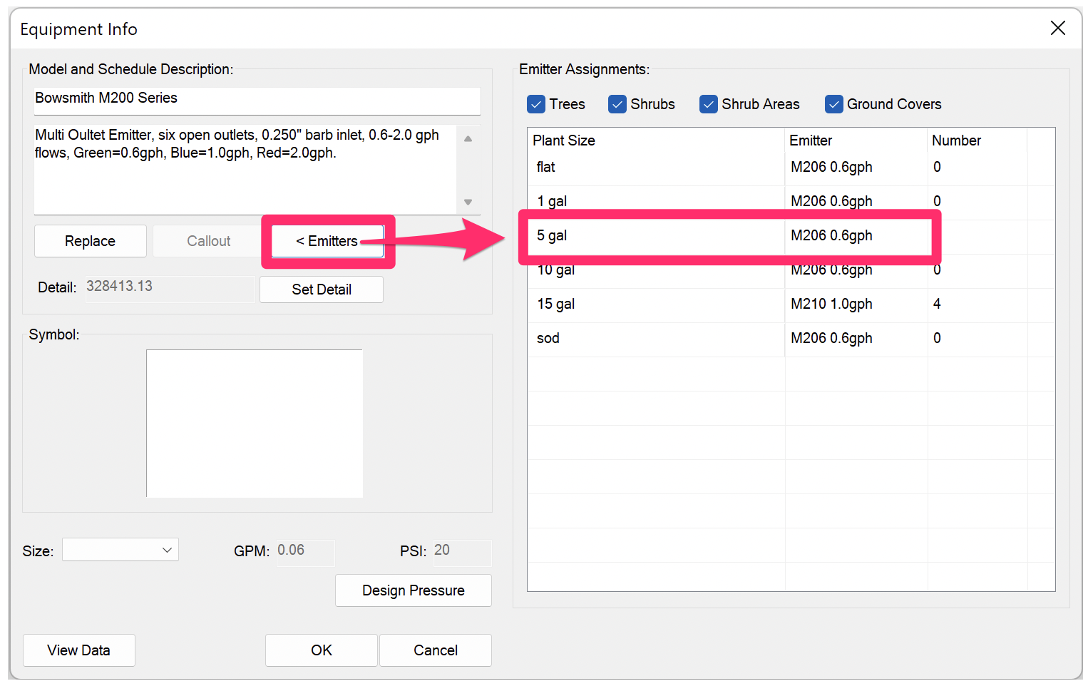
Emitter assignment for the same plant size shown in the Equipment Info dialog box
2F. Still having issues with the flow rate calculation in your drip areas? Any number of possible issues with the planting Xref could still be the culprit. Here are a couple of important pointers:
- If you haven't done so already, detach the planting plan Xref and re-insert it using our fxREF tool, which will help catch many of these issues.
- You can also try detaching the planting plan and instead attaching a simple blank drawing containing just a single plant to help isolate whether or not the issue is with the planting Xref.
Potential issues to address in the planting plan Xref:
If the problem is in fact with your planting Xref, it could be the result of myriad possible issues, such as:
- Drawing corruption, which would require running our drawing cleanup steps on your planting plan
- A nested Xref (an Xref within an Xref). For more information on nested Xrefs, see our description of Xref attachments.
- Your plants may have been disassociated with their data. To check for this issue, place a Plant Schedule to confirm that the plants still have their data attached, and that they are actually project plants and not Concept Plants or Generic Plants. For example, if your schedule is showing that a particular plant has only been placed twice but the drawing is supposed to include several more versions of that plant, those other versions may have lost their data. If a plant doesn't show up at all in the schedule, all placements of that plant may have lost their data. If the data has been removed from one or more of your plants, you have two options:
- Restore a backed-up version of the Land F/X project associated with your planting plan, or
- Use our Mimic Plant Mimic Plant tool to restore your plants' data. Place the correct plant, then run Mimic Plant. Select the plant you just placed as the source object, then select any and all instances of that plant that have lost their data as destination objects. Repeat this step for each plant species that is not showing up correctly, or at all, in the Plant Schedule.
Step 3: Check for issues in the irrigation plan.
Now that we've ruled out issues with the planting Xref, we can go back to the irrigation plan.
3A. Open our Edit Plant tool and select one of the plants.
The plant will be in the Xref, but you should still be able to select it with the tool active.
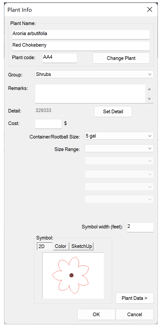
Verify that the Plant Info dialog box comes up correctly.
If not, you either have:
- A missing CAD Service Pack or update, or
- A setting that's preventing the Xref data from copying to your top drawing (i.e., the irrigation plan).
If you do see the Plant Info dialog box (pictured to the left), move on to the next step.
3B. Type PROP in the Command line and press Enter to open the Properties panel.
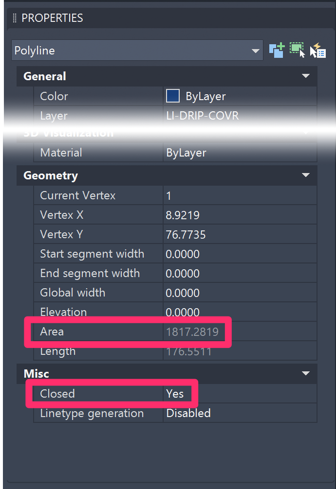
Select the polyline boundary of the drip area, and verify that the Properties panel displays an Area value.
If not, you'll need to address an issue with the polyline boundary, which is likely not closed or possibly includes self-intersections or other issues.
The example to the right shows the Properties panel displaying an Area value for a selected polyline boundary and a Yes value for Closed, both of which indicate that the boundary is correctly closed.
Depending on your specific issue, potential solutions include:
- Runnng the BOUNDARY command on the dripline boundary to turn it into a closed polyline
- Deleting the drip area, redrawing the polyline boundary, and placing the drip area again
Is your drip emitter area showing a flow rate (i.e., not 0), but the emitter quantity and/or flow rate are incorrect?
If you've already sized your laterals and/or have placed an Irrigation Schedule and found that the flows or emitter quantities per container type do not reflect the manual calculation you've completed as a cross-check for the affected planted area, here's what to do.
Drip area boundaries lying within groundcover area boundaries
If a drip area boundary lies within a groundcover area boundary, the drip area will be unable to read the plants in that groundcover area.
This issue commonly occurs with drip area boundaries that were created using a groundcover area boundary that includes arc segments. In this case, the system would have had to convert the drip boundary to all line segments, which in turn would have caused the drip area boundary to fall just within the groundcover boundary, preventing it from reading the plants.
If the drip area boundary is in fact within the groundcover area, you'll need to adjust the drip boundary to be just slightly outside of the groundcover boundary. The system will be able to read and count the groundcover if at least half of its boundary points distinctly fall within the drip area boundary. Also keep in mind that drip areas cannot just include part of a hatch. The drip hatch needs to be entirely within the drip area.
Because the drip area can't read just a part of a hatch, you'll need to split the planting area to the respective drip hatch area. You can generally achieve this split using our handy Polydivide tool – keeping in mind that the shape and area you're trying to divide may affect the tool's ability to work properly.
In the future, if you plan to make drip boundaries from groundcover boundaries, it will save some headache to either decurve the groundcover boundary ahead of time, or to draw it without arcs.
Step 4: Still can't find or fix the issue? Further troubleshooting.
It's now time to turn on the advanced debugging information, which may help diagnose the issue.
4A. Type FXDEBUG in the Command line and press Enter.
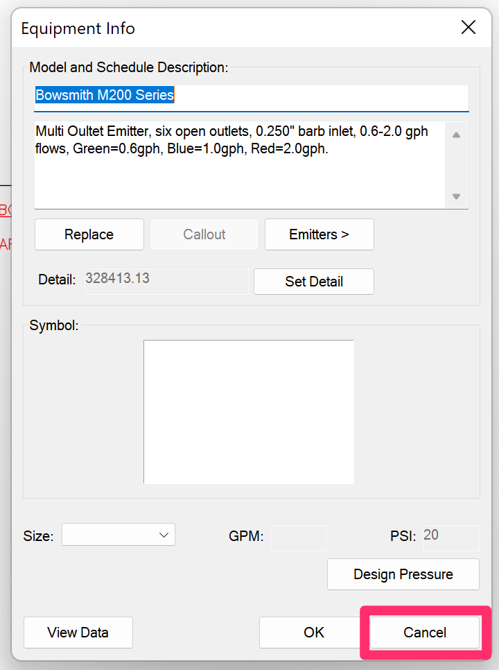
4B. Open our Edit Equipment tool and select one of the drip areas where you're experiencing the issue.
The Equipment Info dialog box will open.
Click Cancel immediately.
4C. Press the F2 key to bring up the Command window.
Here, you'll see an extremely verbose output of the system attempting to correlate plants with that drip area, which may include some information that can help our support team pinpoint the issue.
You're welcome to take a screenshot of this output and send it in to us in a technical support ticket, and we should be able to help.


