Work Areas
Quick video
- Advantages of Creating a Work Area
- Creating a New Work Area
- Placing a Work Area in Your Drawing
- Ignoring Work Areas
- Work Area Titles are Multileaders (MLeaders)
- Nested Work Areas (Work Areas Within Work Areas)
- Work Areas for Scale
- Work Area Layer Suffixes
- Isolating Work Areas and Attaching Them as Xrefs
- Editing Work Areas
- Work Areas for UCS
- Work Areas and Hatches
- Work Areas and Our Highlight Tools
- Work Areas in Xrefs
- Related Webinars
- Troubleshooting
A Work Area functions like a "drawing within a drawing," allowing you to carry out a number of important functions without leaving your drawing. Work Areas allow you to:
- Create a planting, irrigation, or hardscape schedule that shows only items in a specific area of your drawing
- Set unique scales
- Perform error checking
Inserting a Work Area will place a visible border around an area you define. You will be able to perform functions or allow drawing settings to occur uniquely just within that Work Area.
Work Areas are drawn with a non-plot line, and the line color from one to another will vary slightly to distinguish them from one another.
Advantages of Creating a Work Area
Quick video
Functions you can control in different Work Areas include:
Placing a Schedule for Just a Specific Area of Your Drawing
Similar to sheet definition, you may want to create an entire plan and run a schedule for plants, irrigation equipment, site objects, Reference Notes, etc. in just a certain area, such as:
- A specific portion or phase of the project
- Off-site and on-site improvement
- Scope-of-work requirements (for example, certain areas designated as containing tenant improvements, other areas under a general contract, etc.)
Learn how to use Work Areas to limit your project schedules to a specific portion of your drawing. See our documentation on:
Scale
You can set different scales to different Work Areas. Objects within those areas will have the correct scale applied automatically.
Error Checking
If you have an extremely large project, you may want to check for errors in just one area at a time. This can apply to items such as the plant labels or irrigation piping.
UCS Control
You can set up a viewing of the site with a User Coordinate System (UCS) and allow automatic control of the UCS while completing work in any Work Area.
For example, you may be working on a large apartment project covering a city block. You will be viewing this project from each of the four streets that surround it, thus viewing the site differently for each Work Area. Use our UCS tool. If Work Areas have been defined, you'll use a pickbox to determine which Work Area is applicable to which UCS. Now when any work is completed in a particular Work Area, that UCS will be the governing orientation.
Creating a New Work Area
Open our New Work Area tool:

F/X Admin ribbon, New Work Area button

F/X Site ribbon, New Work Area button

F/X Planting ribbon, New Work Area button

F/X Irrigation ribbon, New Work Area button
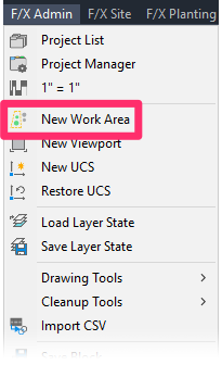
F/X Admin pull-down menu
or type DefineWorkArea in the Command line
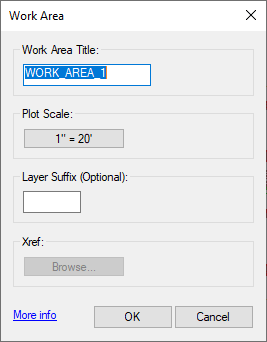
The Work Area dialog box will open.

1. Enter a Work Area Title.
2. Use this button to set a scale for your Work Area. More information
3. If you want, you can also enter a Layer Suffix. The text you enter here will be applied automatically to the names of layers making up all objects placed within the Work Area once you've created it. More information
4. Xref: Our New Work Area tool allows you to save a Work Area as a separate file and then attach it to your drawing as an external reference (Xref). More information
Click OK or press Enter to close the dialog box and begin drawing the Work Area.
Note: The name of the Work Area is not in itself critical, but it can depend on:
- Phases of construction.
- Detail areas.
- On-site/off-site improvements.
- Tenant improvements and developer improvements.
- Alternatives for construction.
- Temporary names. For example, you can use Work Areas to perform error checking on a large site, erase the Work Areas, and add new ones.
Placing a Work Area in Your Drawing
Once you create and name your Work Area, the Command line will prompt: First point [Select].
Click a location in your drawing to begin defining your Work Area.
The Command line will then prompt: Next point [Window]. You can now define your Work Area in one of three ways:
- Continue clicking points in the drawing to define the boundary of your Work Area manually. Type C to Close your Work Area when finished defining the Work Area.
- Type W for Window. After you select this option, moving the cursor in the drawing will create a rectangle that will change in shape and size as you continue to move the cursor. Click to set the opposite corner of the rectangle that will become your Work Area.
- Type S to Select an existing polyline to convert it to a Work Area, or click a location in your drawing to begin defining your Work Area.
When you define a Work Area with an existing polyline, any arc segments in your polyline will convert to multiple straight-line segments. Work areas cannot read the path of an arc.
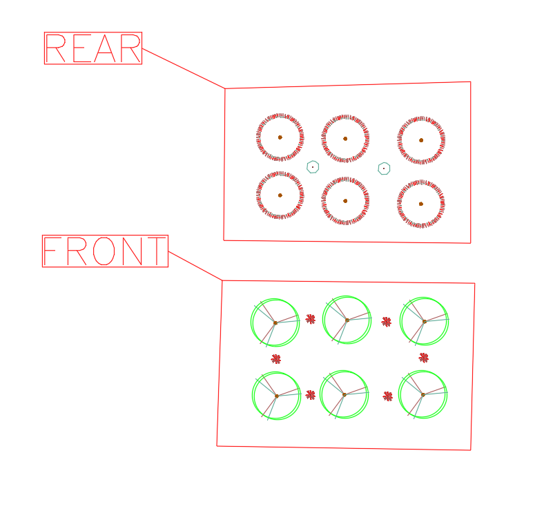
The name you entered will automatically appear beside the new Work Area, and the name and the boundary on a non-plot layer, L-WORK-AREA.
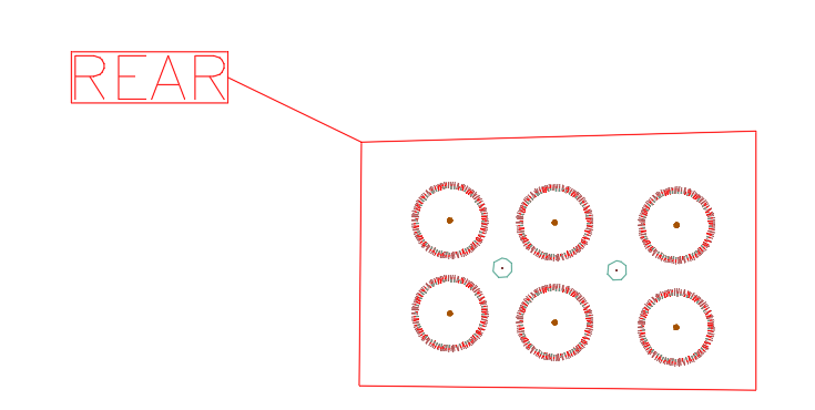
In the example pictured to the right, we've created two Work Areas: REAR and FRONT.
The need to isolate areas of work generally arises with larger-scope projects. The need for Work Areas can arise for several possible reasons:
- The project is large, such as an entire college campus. Create Work Areas so to isolate different areas of work, such as different campuses, etc. You can now perform error checking and place planting or irrigation schedules just within the Work Areas, if you wish.
- The project is a jungle, with intense planting over a large area. Create Work Areas just perform error checking on plant labels in a certain area before you move on to another area.
- The project consists of street improvements over a several-mile-long winding roadway. As the road changes direction, you will want to orient the UCS view of the site differently so it will conform better to your sheet layout, etc. Create different Work Areas and use New UCS to define a UCS that will just apply only in a certain Work Area. You will now be able to use Restore UCS and click on a Work Area. If you do so, you will automatically orient to the UCS of that Work Area, and you will zoom extents to that Work Area in order to view and work within it.
- The project has different scales, such as detail areas. Create Work Areas around the detail areas. When you define a scale, you will be able to select a Work Area. Now any objects within that Work Area will be scaled automatically to the defined scale.
- Work Areas. You can now isolate the amount of work in each area using schedules.
- The project has tenant improvements as well as overall improvements. Complete the design work on one plan, and simply define which areas are for which responsibilities. The schedules, scale, UCS, and error checking will respect the Work Areas.
- The project has phases of construction or has a base bid with alternates. Complete all the design work on one drawing, and then create Work Areas to define the phases or alternatives. You can always run schedules to define the scope of work in all your Work Areas, and then erase and redefine them as necessary. Therefore, if the base bid and each alternative has a certain budget, complete the design work as desired and then keep adjusting the Work Area boundaries to fit the budgets.
Ignoring Work Areas
Are there Work Areas in your drawing but you want to ignore them when prompted? Most Work Area commands include an option for <Entire drawing>. Right-click or press Enter to choose this option and ignore Work Areas.
Work Area Titles are Multileaders (MLeaders)
Work Area titles are now framed MLeaders, giving you more control in editing and moving them. More information about MLeaders
If the title of a Work Area has been lost or deleted, you can now edit that Work Area and replace the title MLeader instantly.
Nested Work Areas
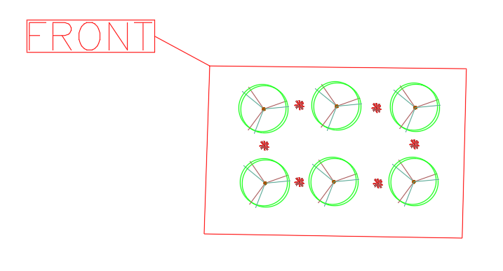
In response to client requests, we've added the ability to create nested Work Areas – that is, Work Areas within Work Areas. Our schedule tools (Plant Schedule, Irrigation Schedule, Reference Notes Schedules, etc.) will now recognize objects within these nested Work Areas. More information
Work Areas for Scale
You can assign a plot scale to a Work Area when creating it. You can also choose to set its scale later by editing the Work Area.
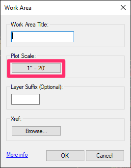
To set a Work Area's scale when creating it, click the Plot Scale button in the Work Area dialog box.
Our Scale tool will open, and you can set your chosen scale for the Work Area.
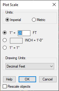
If you set a scale for a Work Area that's different from the scale of the overall drawing, you'll see that scale in its title.
In the example shown below, a Work Area with a scale of 1" = 10' has been drawn around the building, in a drawing with an overall plot scale of 1" = 20'. You can observe the difference in scale for hatches and the labels. To the right, two Reference Note Schedules have been generated: a Work Area–specific schedule at the Work Area scale, and an overall schedule at the drawing's scale.
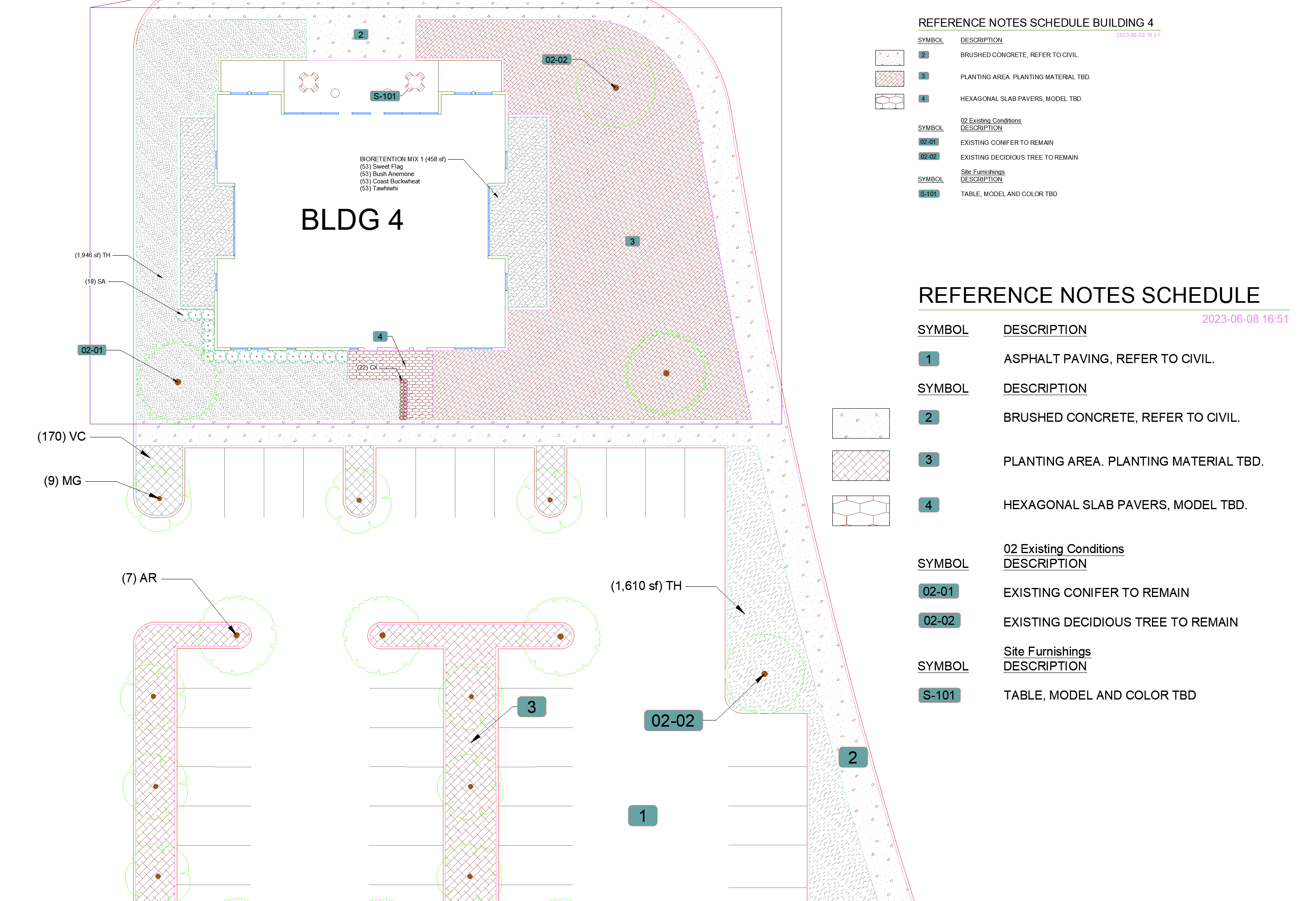
The scale you've set for a Work Area will automatically apply to any work you complete within that Work Area.
When you set a scale for Work Area in a Paper Space viewport, the scale you set should match the scale you've set for that viewport.
Work Area Layer Suffixes
The New Work Area dialog box includes an optional Layer Suffix setting. If you choose to assign a layer suffix to a Work Area, all objects subsequently placed in the Work Area will have that suffix added to their layer names. These include plants, plant labels, any block or hatch, irrigation components, and even irrigation pipes you draw within a Work Area.
In this example, we'll enter the layer suffix PARK for a new Work Area we've also named PARK.
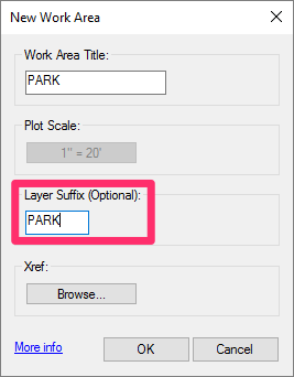
As a result, all objects placed within this Work Area in the future will have the suffix -PARK added to their layer names. This feature makes it extremely easy to locate layers within this particular Work Area. If you find yourself wanting to perform an action on objects within a Work Area – such as freezing or locking layers – this feature can come in extremely handy.
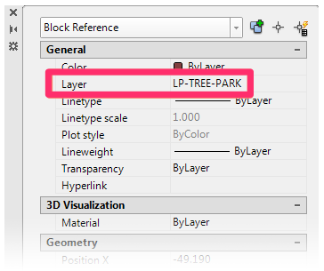
For example, any tree placed within the Work Area will be on the layer LP-TREE-PARK. (Trees are normally on the layer LP-TREE.)
Layers making up objects within the Work Area will now show up as separate layers in the Layer Properties Manager, with the suffix at the end of their names. This delineation makes it easy to locate and, for example, freeze layers within the Work Area.

The layer suffix will only be applied automatically to objects placed within the Work Area after the Work Area has been created and placed. If you draw a Work Area around existing objects, you can use our Match Plant and Match Properties tools to apply the suffix to blocks and hatches already within the Work Area.
The following irrigation-related items now support the Work Area Layer Suffix setting:
- Pipe fittings
- Our Draw Pipe features (i.e., Draw Lateral and Draw Mainline)
- Pipe labels
Applying a Layer Suffix to Existing Objects
If you create a Work Area and draw it around existing objects in your plan, you'll need to take a few extra steps to apply the layer suffix to those objects. In this example, we'll draw a Work Area around some existing trees and other objects in a drawing.
Because we've drawn this new Work Area around existing objects, those objects will retain their original layer names (without the suffix) until we apply them manually to one type of object at a time. This process works with all blocks and hatches, including plants, Reference Notes, irrigation equipment, and "dumb" site blocks such as Plan Graphics and Elevation Graphics.
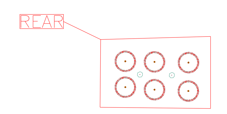
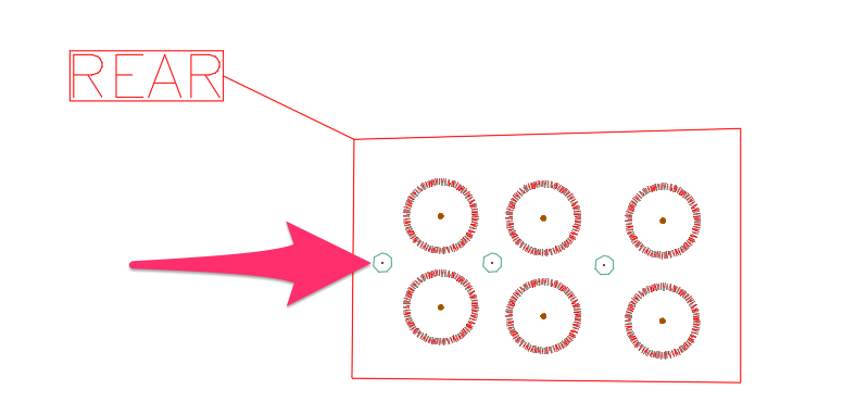
First, use our Match Plant tool to select an object within the Work Area and place a copy of that object anywhere within the same Work Area. In our example, we'll use Match Plant to copy one of our shrubs and place the copy off to the side – taking care to place it within the Work Area.
Because we've placed it after creating the Work Area, the copy will automatically have the new layer suffix applied to it.

Now open the Match Properties tool and select the copy of the object you've just placed (in our example, the tree) as a "source object."
You can now draw a window to select all trees of the same variety within the Work Area as "destination objects" to take on the properties of the copied object – including the layer suffix. Because Match Properties only recalls the exact object selected as the "source object," the window can include other objects. The properties will only be applied to the same type of object (in our example, a particular variety of tree) as the "source object."
Don't forget to delete the copy once you've applied its properties to the others.
You can now repeat these steps for each other type of object in the Work Area. (Of course, you can save yourself these steps by creating Work Areas first and then placing objects within them.
Isolating Work Areas and Attaching Them as External References (Xrefs)
Our New Work Area tool makes it easy to isolate Work Areas, save them as separate files, and Xref them back into your drawing. This feature is a handy way to keep your drawings organized by keeping your Work Areas separate from each other.
In most cases, you'll save all your Work Areas into one separate file. You'll then Xref that file into your site plan, irrigation plan, planting plan, drainage plan, emergency access plan, etc. However, this feature also allows for some cool variations. For instance, you could have one Xref that contains all the Work Areas by sheet (which you are primarily doing). But you can then have a second Xref if, say, sheets 1 through 3 are being built in Phase 1, sheets 4 through 7 in phase 2, etc. If necessary, you can detach/reattach between the two Xrefs to achieve different results.
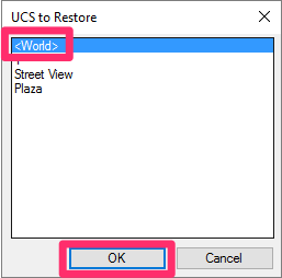
First, draw your Work Areas, making sure you're in the World Coordinate System (WCS).
You can apply the WCS to your drawing quickly by opening our Restore UCS tool, selecting <World>, and clicking OK.
Next, isolate the layers of any Work Areas you want to save into a separate file and Xref back in.
You can easily isolate the layers of one or more Work Areas if you've used our Layer Suffix feature.
Use the WRITEBLOCK (WBLOCK) command to select your Work Areas and save them into a separate file.
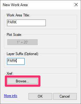
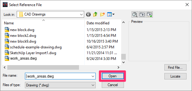
To attach your Work Areas back to your drawing as an Xref, open the New Work Area tool and click Browse.
Browse to the DWG you just created using the WBLOCK tool, and click Open.
Your Work Areas will now be attached to your drawing as an Xref.
Editing Work Areas
You can now use our Edit Object tool to edit the data you've assigned to your Work Areas.
Open Edit Object:

F/X Site ribbon, Edit Object option
Type FX_ObjInfo in the Command line
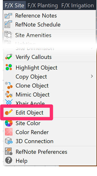
F/X Site menu, Edit Object option
Select the Work Area you want to edit. You can select either the Work Area boundary or its callout.
The Work Area dialog box will open, and you can make any necessary changes.
Replace a Missing MLeader Work Area Title
If the MLeader title of your Work Area is missing – for example, if you moved the title and lost it, or copied the Work Area between drawings and forgot to copy the title – you can replace it automatically by simply editing the Work Area.
Note that we don't recommend the practice of copying Work Areas between drawings. Instead, we recommend using Work Areas in Xrefs.
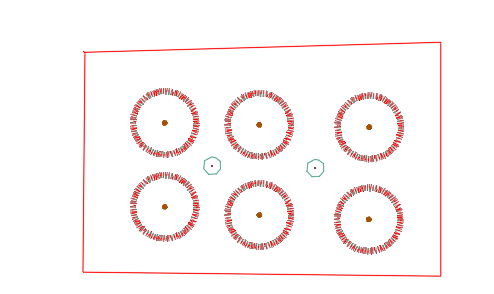
In this example, we'll use the Edit Object tool to select a Work Area that's missing its MLeader title.
After we close the Work Area dialog box, the MLeader title is replaced – whether or not we've actually made edits to the Work Area.
If the Work Area title shows up in a location where you don't want it, you can easily grab it and move it to the location of your choice.
Work Areas for UCS
Once you have defined one or more Work Areas, the cursor will turn into a pickbox when you open our UCS Definition tool. You can either select a Work Area, or right-click to set that UCS definition for the whole site. If you select a Work Area, you will zoom extents to that Work Area, and the UCS will be set as you defined it.
Work Areas and Hatches
Once 50% of the boundary points of a hatch are found within a Work Area, 100% of that hatch will be calculated as lying within that Work Area.
Our software currently does not allow you to split a single hatch between multiple Work Areas. Splitting hatches in this way is not possible for a number of reasons – primarily because the only way to do so is to convert every hatch to a Region object, and then perform a Union and Subtraction against the Work Area in order to determine the area inside vs. outside the hatch.
This process can misfire because not all hatches can be converted to Region objects. Allowing splitting of hatches would require the software to highlight those areas in some fashion to alert users to them. But more importantly, that process of converting to Regions and Union/Subtracting takes time. For a complicated design with hundreds of areas could easily chug the computer for a number of minutes. While of course some users would be willing to accept that hit, we feel it's a bit beyond the acceptable range of about 7 seconds for the computer to finish doing whatever it was doing.
Even more importantly, splitting jobs into zones or phases typically coincides with a desire to turn off or half-tone the objects outside of the current viewport. In order to do this, you would need to draw the hatch as two separate hatches, or simply split it in two.
Need to split a hatched area into two or more regions? You can easily do so with our POLYDIVIDE tool.
We also recommend avoiding having Work Areas and hatches share boundaries. A shared boundary can prevent a hatch from calculating correctly within the Work Area.
Work Areas and Our Highlight Tools
If you use our Highlight Plant or Highlight Object tool on a plant within a Work Area:
- Only plants in the same Work Area will be highlighted, and
- If you type A for Additional plants after running one of the Highlight tools, only additional plants within that Work Area will be highlighted.
Work Areas in Xrefs
Quick video
Our software recognizes Work Areas within or Xrefs. That means you can run a schedule that includes plants, irrigation equipment, or site amenities within Work Areas that exist in files you've attached to the main drawing. When you go to generate your schedule, you can simply select individual Work Areas in your Xrefs as if they are in the current drawing. If you select All Work Areas, Land F/X objects within Work Areas in your Xrefs will be included in the schedule as if those Work Areas were in the main drawing.
For more information and specific instructions, see our Work Areas in Xrefs documentation.
Related Webinars
- Using Work Areas: Work Areas provide a perfect way to organize your schedules, scales, layers, and User Coordination Systems (UCSs). Whether you need to separate out phases in your schedules or show an area at a different scale and viewing angle, you need to know how to manipulate a Work Area. (1 hr 2 min) Planting F/X for Beginners Part 2: In this second installment, we'll dive right into some of the tools you need to know about for the best experience and fastest workflow when starting with Land F/X planting plans, including how to use Work Areas. (1 hr 3 min)
- Common Land F/X Questions: This webinar covers some of our lesser-known tools, including Work Areas. (1 hr)
Troubleshooting
General Work Area troubleshooting
Issue: You want to set different scales in your drawing
Issue: Work Areas are not recognizing or calculating a hatch
Issue: You are unable to create or place a Work Area
Issue: "Cannot find Work Area title" error message when placing a schedule in a drawing with Work Areas


