Set the Scale & Units
Quick video
- Scale & Units Overview
- Setting the Scale & Units
- Annotative Scaling
- Rescale Objects
- Correcting the Scale of Objects in Your Drawing After Changing the Scale
- Scaling & Units Theory
- Assigning a Real-World Scale to a Placed Hatch Pattern
- Imperial-Metric Scale Conversion
- Related Webinars
- Troubleshooting
The scale of your drawing plays a critical role in how information and symbols are displayed, how they will appear in the final product, and, in the end, how they will plot.
You should never need to set the Land F/X Plot Scale to 1:1. You may draw at 1:1 in Model Space, but the Plot Scale refers to the scale for Paper Space for the proper sizing of text and hatches.
Make it a habit to ALWAYS set your units and scale before you begin work on a drawing. Taking the time to plan and set your units and scale early will prevent unnecessary stress in the future – not to mention save you hours of time.
Scale Overview
Quick video
Most of your work takes place in Model Space. However, it's also important to translate your drawing to a viewport in Paper Space. This will allow you to view a portion of the site at a certain scale when you plot your drawing.

Be sure to review how your units are formatted in AutoCAD – an important consideration with scaling. Your drawing might be scaled in architectural or engineering units, with one unit being one inch, or decimal units, where one unit represents one foot or one meter, as determined by your setting of the insertion scale.
Check your units by typing Units in the Command line and pressing Enter. The Drawing Units dialog box will open.

Check the Drawing Units dialog box to find out the units you've set for your drawing (or the units that have been set by the consultant, colleague, or client who sent you the drawing).
More information about units in AutoCAD
You can also verify your units in Model Space by drawing a line in your drawing. For instructions on this effective verification method, see our Verify Your Units article.
Setting the Scale & Units
Open our Scale tool:

F/X Admin ribbon

F/X Site ribbon

F/X Planting ribbon

F/X Irrigation ribbon
Or type SetDrawScale in the Command line
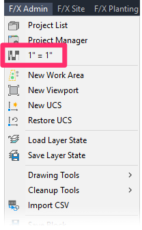
F/X Admin pull-down menu
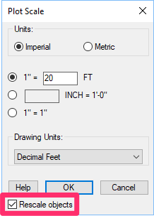
The Plot Scale dialog box will open. Here, you can set your scale in either Imperial or Metric units.
Set the scale once and forget it; all objects in your drawing will automatically be scaled correctly. You can also set Multiple Scales in One Drawing.
Imperial Units
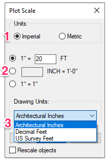
1. Select the Imperial option to set an Imperial scale and set your units in inches or feet.
2. If you choose to set an Imperial scale, you have three scaling options. Select one of the three options to set your scale:
- 1"=__FT: Select the top radio button to choose the number of feet represented by 1 inch in your drawing. In our example, we have selected the top radio button and set our scale at 1"=20FT (1 inch = 20 feet).
- __IN=1'0": Select the middle radio button to choose the number of inches in your drawing that will represent 1 foot.
- 1"=1": Select the bottom radio button to set a life-size scale (i.e., 1 inch in your drawing will actually represent 1 inch at the project site).
3. Use the Drawing Units pull-down menu to select between Architectural Inches (e.g., 1 foot 6 inches), Decimal Feet (e.g. 1.5 feet), or US Survey Feet.
We recommend using Architectural Inches for items such as details, where precision is integral. For site plans, where most contractors will not work with precision to the nearest 1/16 inch, for example, we prefer Decimal Feet. Your selection will depend on your personal preferences and/or your office standards, however.
US Survey Feet
We've added a new setting of US Survey Feet to the Plot Scale dialog box as an additional Drawing Units option for Imperial units.
This setting is only available for AutoCAD or F/X CAD versions 2017 and newer. If you plan to share files with users who have AutoCAD versions older than 2017, keep in mind that your files will not automatically scale correctly when inserted into drawings opened with those versions.
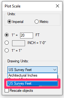
So, what is this setting, and why would you need to use it?
A 1959 international agreement codified the international foot as a length of exactly 0.3048 meters. The US Survey Foot corrects this estimation, making it closer to 0.3048006 meters. If you need to deal with particularly large sites referencing the State Plane Coordinate System (SPCS), or even GPS coordinates, the US Survey Foot offers more accuracy than Decimal Feet. How much more? That difference exceeds 2 feet for every 200 miles. The vast majority of SPCS-based drawings we've seen have been plans for sites lying more than 300 miles from 0,0. That's why we highly recommend using the US Survey Feet setting if you're working with SPCS coordinates.
Finally a bonus side effect of this new unit type is that it's incompatible with 2007 Proxy Objects – a common source of drawing corruption. If you've been suffering from the unwanted scaling of drawings due to the -DWGUNITS bug, this setting is another way around that issue.
Metric Units

1. Select the Metric option to set a Metric scale and set your units in meters, centimeters, or millimeters.
2. If you choose to set a Metric scale, you'll set your scale in terms of a ratio:
- If you select the top radio button, you can then use the pull-down menu to select the ratio between the size of objects in your drawing and the actual objects you are designing. In our example, we have selected the top radio button and set our scale at 1:20. As a result, an object in our drawing will represent an object 20 times its size.
- 1"=1": Select the bottom radio button to set a life-size scale (i.e., 1 centimeter in your drawing will actually represent 1 centimeter at the project site).
3. Use the Drawing Units pull-down menu to select between Meters, Centimeters, or Millimeters.
AutoCAD is by design considered "unitless." The definition of a line in AutoCAD is always something like "0,0 – 10,10." In this case, the line is extending from the coordinates 0,0 to the coordinates 10,10. Note there is no Unit specified – just the numeric coordinates. So no matter what you change the units of the drawing to be, the line will still extend from 0,0 to 10,10. So in a rather ironic way, "unitless" is hardly so. In fact, it actually is quite the opposite; it is very much hard set to a unit type. What does this mean for you as the designer? You need to be extremely diligent in confirming the units.
Setting the Scale in a Paper Space Viewport
You can also use our Scale tool to set the plot scale for a Paper Space viewport.
To set a scale in a Paper Space viewport, double-click within the viewport to make it active.
Select No from the Display Locked menu in the Properties panel.
The viewport will be unlocked.
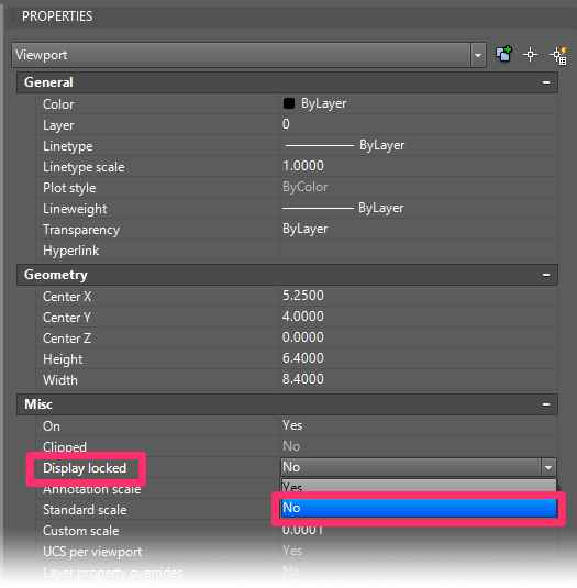
The following sequence of steps is meant to help keep everything in view while you set your scale properly through your viewport. Once the scale are set, you can lock the viewport again.
Center your view in the viewport, and make sure it's set to a 1:1 scale. You can then use the Scale tool to set the scale for that viewport.
You'll be asked whether you want to scale the active viewport. Click Yes. The viewport will be scaled as you've set it.
Center your view in the viewport again, taking care not to zoom in or out.
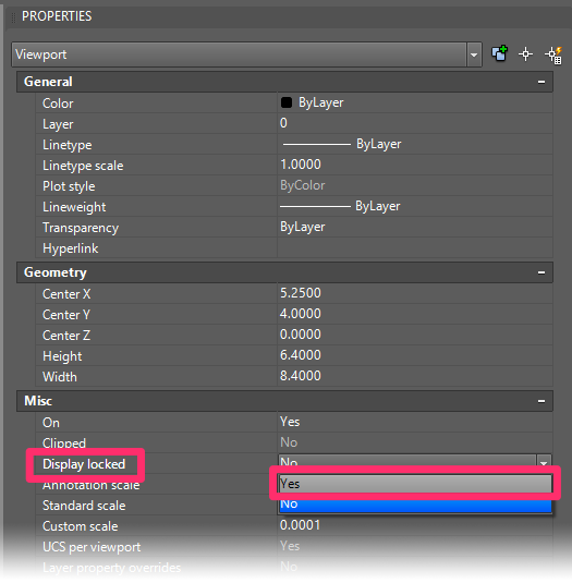
With the viewport still active, select Yes from the Display Locked menu.
The viewport will be locked.
Annotative Scaling
Prior to 2015, the scaling dialog box included an option to Use Annotative Scaling.
We found that Annotative Scaling was causing major problems for many users who had mistakenly selected this option.
For that reason, we've removed the Annotative Scaling option from the dialog box. Annotative Scaling is now available as a keyboard command: LANDFXANNO.

The Annotative Scaling option is no longer available in the scaling dialog box.
You should only use Annotative Scaling if you want to show your plan at multiple scales.
If you don't need to display your plan at multiple scales, a better practice would be to define your scale before placing labels. In the future, if you aren't preparing multiple scale views of the same site, there is frankly no reason to use annotative scaling. You could avoid this option altogether – along with all the potential hassle it can bring.
Want more reasons why you shouldn't be using Annotative Scale? Find out here >
Turn Annotative Scaling On/Off

If you still want to use Annotative Scale, type LANDFXANNO in the Command line and press Enter. The following dialog box will display whether Annotative Scaling is currently turned on or off. If Annotative Scaling is on, click Yes to turn it off. And vice versa.
Want to use Annotative Scale for your planting and/or site hatches? Here's how.
Rescale Objects
If, for some reason, you decide to change the scale later in the project cycle, you can always change the label scales manually by checking Rescale Objects.
Note that this option will only rescale objects from the current scale to a new scale you set. If you don't change the scale when you select this option, objects in your drawing will not be rescaled.
The Rescale Objects option will now work on Multileaders (MLeaders) in your drawings.
Correcting the Scale of Objects in Your Drawing After Changing the Scale
Changing the scale will not change the scale of objects that already exist in your drawing. Therefore, if you change your scale, you will need to correct the scale of all plants, Reference Notes, and any other objects that were in the drawing before you changed the scale.
Here's how to correct the scale of existing objects:
Select one of the overly large or small objects.
Right-click the selected object, and select Select Similar from the menu that opens.

Change the scale in the Properties panel to your new scale.


The new scale will be applied to all selected objects. (You may have to repeat these steps a few times to rescale all existing objects, but it's quicker than redoing them one by one.
For future reference, this is a great opportunity to remember why it's so important to set the scale before beginning work on a drawing: So you don't run into issues like this!
Scaling & Units Theory
Scale can be a confusing issue. Here are some tips:
Model Space is without scale (or it is drawn at full scale), and scale is not important until you want to enter text, dimensions (which require text and arrow sizes), callouts, hatch patterns, etc., or simply want to plot it. In these cases, scale (specifically, plot scale) becomes extremely important. The plot scale will determine how you will plot the Model Space in the Paper Space layout tab.
Metric unit drawings are quite simple. In the Drawing Units dialog box (reached by typing UNITS in the Command line), the Unit Type is formatted for decimal units with Insertion Scale – or what one AutoCAD unit is understood to be – set at Meters. While you can format your units and set the scale for Millimeters in Model Space, this is undesirable for the size and math required for site work. If you receive a CAD file from another source with the Unit Type set to millimeters, you are best served to reduce the plan by 1/1000 and reformat the units for meters. This is your choice, however.
With Imperial Units, you would set the Unit Type to either Architectural or Engineering. The Insertion Scale should be set to Inches for each of these unit types. A common practice for civil engineers and surveyors is to set the Unit Type to Decimal, and the Insertion Scale to Feet. In this case, one AutoCAD unit is assumed to be one foot).
In some cases, you won't know the drawing units, which will affect how the scale is to be set. In this case, you may just assume they are set correctly. Imperial plans offer two possible options:
- Decimal Units, commonly used by civil engineers and surveyors. With this setting, one AutoCAD unit is understood to represent 1 foot, even though an AutoCAD unit is technically unitless. This setting can prove extremely handy for various civil or survey functions, as it doesn't require you to enter a unit symbol (') when entering numbers for distance or direction.
- Engineering or architectural units (Imperial Units), often, though not always, are used by architects and many landscape architects. This is where one AutoCAD unit represents 1 inch, and is expressed with decimal inches for engineering (for example, 10'-4.625”) and with feet and Imperial inches for architectural (for example, 10'-4 5/8”).
- These settings commonly cause confusion in office situations. The civil will often give the building architect a site base in decimal units, the architect enlarges it by a factor of 12 for architectural units, and then gives that site base to the landscape architect in architectural units. The landscape architect now has to coordinate with the civil, but they are using different units. All this interaction requires careful attention to the drawing's units.
You often need to set the units manually when you first receive a site plan from someone else. Use AutoCAD Distance Command (Tools/Inquiry/Distance) to measure an object with a known length, such as a door or a parking stall. Then determine the distance in the AutoCAD Command line, paying careful attention to the units. Some combinations of results in the AutoCAD Command line for measuring a door could include:
- Distance = 36.0: This plan is set for Decimal units (we know this because no units follow the number). However, 36.0 corresponds to a 36” door, and one unit should represent 1 inch. The units are formatted incorrectly, and you would set the units (Format/Units) from Decimal to either Engineering or Architectural (Imperial Units).
- Distance = 3.0: This plan is set for Decimal units (again, we know this because no units after the number), and 3.0 would correspond to a 36” door in Decimal units where one unit represents 1 foot. The units on this plan are correctly set to Decimal Units.
- Distance = 3”: This plan is set for Imperial units but should be set for Decimal, so one unit will represent 1 foot. The units are formatted incorrectly, and you would set the units (Format/Units) from Imperial to Decimal.
- Distance = 3'-0”: This plan is set for Imperial units and is correct.
Assigning a Real-World Scale to a Placed Hatch Pattern
You might want a hatch that shows pavers, wood planks, or other objects to appear at a scale where the hatch components show at the same measurements in your drawing as they would on the site itself. For example, you might have a hatch depicting 8-inch pavers, and you want the pavers to actually measure 8 inches in your drawing. If so, here's what to do.
Imperial-Metric Scale Conversion
Looking for a way to convert a site plan from Imperial to metric and wondering what standard metric scale you should use in the new viewport, or vice versa? Trying to save in a detail into your Imperial detail library that was originally metric? See our Metric and Imperial conversion cheat lists.
Related Webinars
- Working With Scale: Proper scale practice is not only essential to Land F/X but to the entire fields of landscape and irrigation design. In this webinar, we do some scale troubleshooting and show you when and how to use scaling techniques such as splitting your drawing into different scales, scaling details, and changing the scale of your entire drawing. (1 hr 4 min)
- 101: First Steps with Land F/X: Learn what Land F/X is, how and why it works, and how you can navigate through your first steps, including sheet setting the scale and units. (1 hr 1 min)
Troubleshooting
Issue: Layers disappear when I change my Viewport Scale
Issue: Blocks are coming in at the wrong scale
Issue: You want to set and label multiple scales in one drawing
Issue: Some of your labels or callouts are not resizing when you rescale your drawing
Issue: Your plant labels are rescaling immediately (to the incorrect size) when placed in Paper Space
Issue: You need to rescale the plant code in one or more of your Alphanumeric plant symbols


