Change Land F/X Line Colors & Block Layer Colors
Quick video
- Step 1: Determine the Land F/X Line Colors to Change
- Step 2: Use Block Layer Colors in Preferences
- Step 3: Change the LFX Plot Style Table
- Step 4: Manage and Maintain the Color Conversion
- Step 5: Save Your Settings in a Layer State
- Layer Colors and XML Files
- Updating Drawings with Existing Land F/X Blocks
- Print Preferences
- Related Webinars
- Troubleshooting
Our block colors – or, more accurately, the layer colors in our blocks – are fully customizable. You can change each layer's line color to meet your office standards.
Looking for a way to change your layer names? See our Layer Names documentation. However, keep in mind that we've named our layers very specifically, following CAD layer naming standards.
Before changing the default Land F/X line colors, download the following documents.
To download each file, right-click and select "Save As" or "Save Target" from the menu.
Step 1: Determine the Land F/X Line Colors to Change
Use the Land F/X Line Color Worksheet (linked above) to determine which of the Land F/X colors conflict with your current office standards – that is, colors that you also use, but that you plot at a different lineweight.
-
Look at each Solid Line color number under the heading LFX Pen Color. View the width in which our software plots this color. If your office does not use this color, or, when you use this color you plot it at, or very near, the same width as our software does, put a check mark in the OK (No Conflict) column. If your office uses this same color and you plot it at a different line weight, put a check mark in the Conflict column.
-
Check for conflicts with the Irrigation Pipe lines, which are plotted solid, as well as the Non-plot Lines, which are screened for a "0" percent screening.
-
Check for conflicts with the Screened Lines, which have a width and a percentage of screening.
You don't necessarily need to change every one of our colors to meet your office standard. You only need to change the Land F/X colors that are also used by your office. Thus, using our software may add some additional colors to the resulting CTB plot style, but you can continue to simply use the colors you've used in the past to create your site plans and drawings.
Step 2: Use Block Layer Colors in Preferences
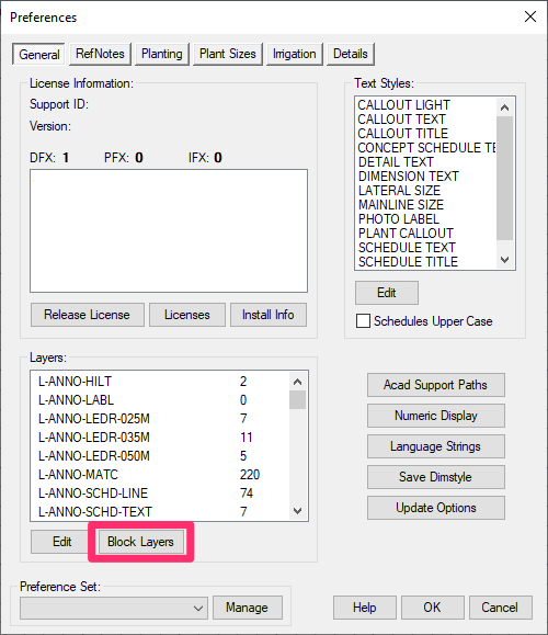
Open the Land F/X General Preferences, then click Block Layers.


The Block Layer Colors dialog box will open.
Here, you'll see a list of the 255 colors used by AutoCAD as index colors for plotting.
The colors used by our software have an asterisk (*) next to them.
Using your Land F/X Line Color Worksheet as a guide, edit each color used by our software that conflicts with your office standards.
You’ll notice that the colors 0 and 2 are not in the worksheet. We left them out deliberately because the layers on color 0 and 2 are not attached to objects that would plot in those colors, so you don't need to change them.
Editing a Block Layer Color
In the Block Layer Colors dialog box, highlight the color you would like to edit.
Then click Edit.

The Edit Block Layer dialog box will open.

1. Land F/X Default Layer Color
2. Color and/or lineweight to convert to
3. This menu shows our default plot width for gthe selected layer automatically. If you want, you can select a different plotting thickness or, if applicable, a named plot styls (STB style).
4. This field shows a description of the selected color. You can type a description or add to the existing description.
5. Click OK to save your changes and move on to another color – or finish editing.
Do you use named plot styles (aka STB styles)? If so, see our instructions for assigning STB styles to block layers.
Continue for all colors that require changing in order to meet your office standards.
It's a good idea to record any additional or final changes you make while using this function by noting them on the worksheet.
When you click OK, you'll see a message asking whether you wish to apply this color transformation to the current file. If you click Yes to apply the layer color changes, the changes will occur drawing wide – not just specific to Land F/X blocks. We recommend opening the LFX Pens.dwg drawing (linked at the top of this article), then applying the color change process to it.
Once you've made all the necessary color changes to the LFX Pens.dwg drawing, you'll need to plot it with a revised CTB file (see Step 3 below).
Step 3: Change the LFX Plot Style Table
After running the layer color changes on the drawing LFX Pens.dwg, plot the drawing to find out whether the line weights appear correct. To do so, you will need to revise the Land F/X LFX.ctb plot style table by combining your office standard CTB plot styles with this plot style. This file would have been loaded automatically into your AutoCAD Pot Style Table Path when Land F/X software was installed on your computer.
Type Plot in the Command line, then press Enter. The Plot dialog box will open.
Expand the dialog box by clicking the right-facing arrow in the lower right corner.

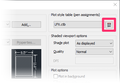
Select LFX.ctb from the Plot style table (pen assignments) pull-down menu.

Once you've selected LFX.ctb, click the Edit button just to the right of the pull-down menu.


The Plot Style Table Editor for the plot style LFX.ctb will open.
Select the Form View tab.
You'll essentially need to merge your office standard color plot widths into the Land F/X LFX.ctb color plot styles. From the Form View of the AutoCAD Plot Style Table Editor, go to each of your office standard colors and ensure that each color’s plotting requirements matches your office standards, such as its Lineweight, Screening, etc. Save this plot style with a different name, perhaps reflecting your company and Land F/X, such as XYZ-LFX.ctb.
Use this new plot style to plot the changed LFX Pens drawing, and check whether the lineweights are presented properly. Note that the plotted lineweights in each lineweight category should look like the same width, and that the category of widths should become wider as the lineweight increases, and the screened lines should match the screen intent.
If any of the lines are obviously incorrect, you may need to change or revise the following:
-
Go back to the revised CTB, and review the Properties of the color in question.
-
Examine the changed LFX Pens drawing using the AutoCAD Properties command (type PROPERTIES in the Command line).
-
You also may not have correctly changed the colors on our Change Colors feature. If this is the case, don’t save the changes to your LFX Pens.dwg drawing. Instead, close and reopen it, then go back to Preferences and select Convert Colors again.
Step 4: Manage and Maintain the Color Conversion
When you confirm the color conversion to apply from the Block Layers button, these changes will be saved into a Setup.GCL file in your LandFX folder location.
The color conversion chart will also be saved with the current Preference Set.
We recommend that you back up your Preference Set.
The Setup.GCL will be created as an additional backup level.
A Layer State is a file that stores your layer settings, such as colors, lineweights, names, etc.
Once you've changed all your line colors and other settings to meet your standards, you'll need to save them into a Layer State. You can create different Layer States to apply to planting plans, details, and other types of drawings.
See our Save Layer State documentation for instructions.
Layer Colors and XML Files
Once you've changed your block layer colors, the system will scan through all folders containing blocks and details. It will then create or verify an XML file with the same filename of each block or detail.
For instance, if you have a block named BENCH-O-10.dwg, that same block folder will also contain the file BENCH-O-10.sld. This file will be used as the preview for the block. In addition, the folder will contain the file BENCH-O-10.XML, which our software will use to determine whether the block's layer colors need to be converted.
Updating Drawings with Existing Land F/X Blocks
If you have existing drawings with Land F/X blocks you'd like to update to match the new block layer settings, we recommend using our BatchMan tool.
Print Preferences
Did you know you can print out all the layer and color settings saved in your Preference Set for quick review and reference? Just use our Print Preferences feature.
Related Webinars
- Customize for Office Color Standards: This webinar covers the necessary tools and techniques for a black belt in the art of office standards – from CTB plotting files to valuable Land F/X tools that enable instant layer color conversions and office color setup. (1 hr 2 min)
- Customizing Land F/X: Learn how to work with specific blocks, layer names, sheet protocols, and other distinct elements that make up your firm’s practices and preferences. (1 hr 3 min)
- Setting up Templates and Preferences for Repeat Clients: To save time and increase your accuracy, learn how to deliver a consistent drawing package for your repeat clients by setting up project templates and Preference Sets. (50 min)
Troubleshooting


