Circuiting
Quick video
- Circuiting Overview
- Creating New Circuiting Zones
- Editing Zones
- Merging Zones
- Filtering Your List of Zones
- Head Tally
- Uniformity
- Flow Total
- Adding to an Existing Zone
- Placing a Zone Schedule
- "No Flow Total for Selected Head Type" Message
- Undocking the Circuiting Manager
- Related Webinars
- Troubleshooting
Our Circuiting tool provides a quick and flexible method of grouping the heads in your design into valve stations. You can use our Circuiting tool to determine the necessary number of valves for each head type in your drawing, calculate the flow (GPM) of a group of heads, and place a schedule listing these numbers for your reference.
Important note: Some Irrigation F/X users have attempted to place callout text in their drawings by copying and pasting the text from one of their Circuiting zones and then changing the text to create the callout. Do not do this! Copying and changing zone text will create problems with your zones and prevent you from being able to use the Circuit tool. Instead, please use our Text tool to place callout text.
Circuiting Overview
Quick video
Circuiting now shares a docked palette with our Schematic Irrigation tool. See the "What's New – Circuiting" video at the top of this page for a description of our updates to Circuiting.
Want to undock this palette? See our documentation on docking and undocking the Irrigation Manager and Schematic Irrigation / Circuiting palette.
Open the Circuiting tool:
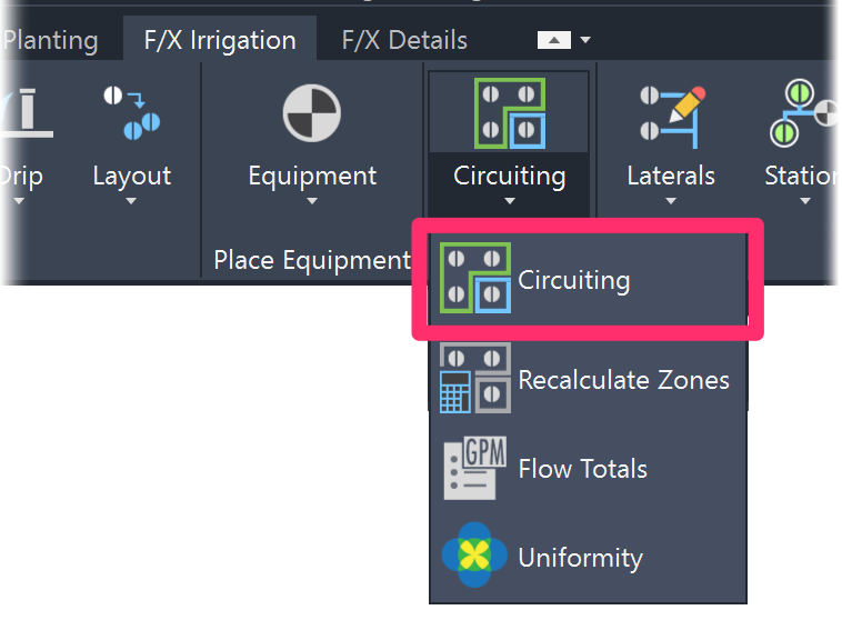
F/X Irrigation ribbon, Circuiting button
or type GPMCalc in the Command line

F/X Irrigation menu, Circuit option
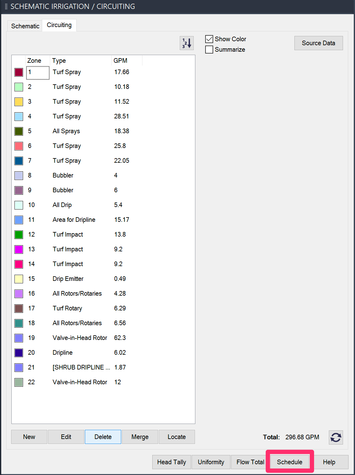
The SCHEMATIC IRRIGATION / CIRCUITING dialog box will open.
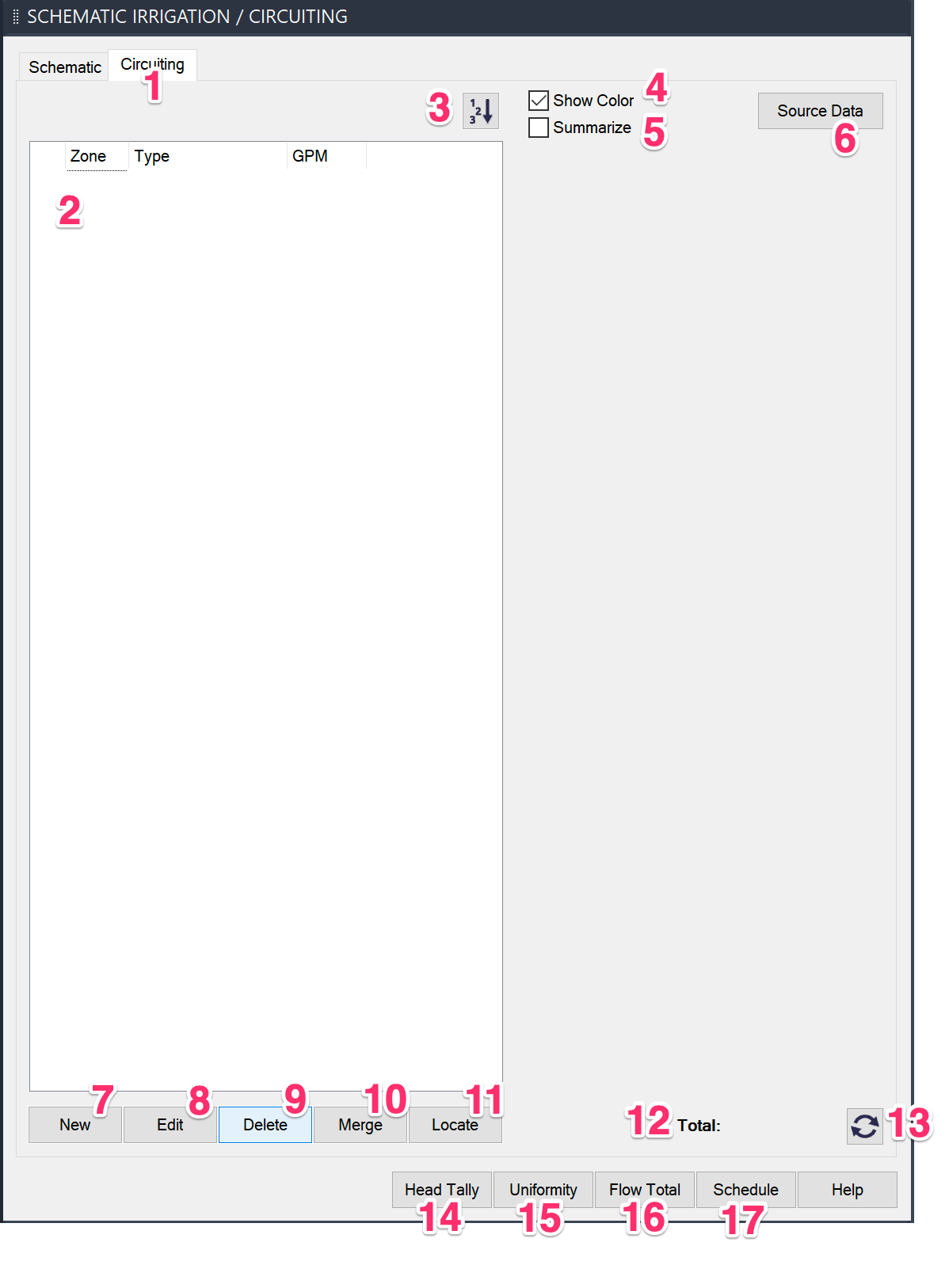
1. Ensure that the Circuiting tab is selected.
2. As you create zones, they'll be listed here. Note that the list will be blank until you've added one or more zones to your project.
3. If you have gaps in your zone numbers after deleting or reordering zones, click this button to renumber your zones.
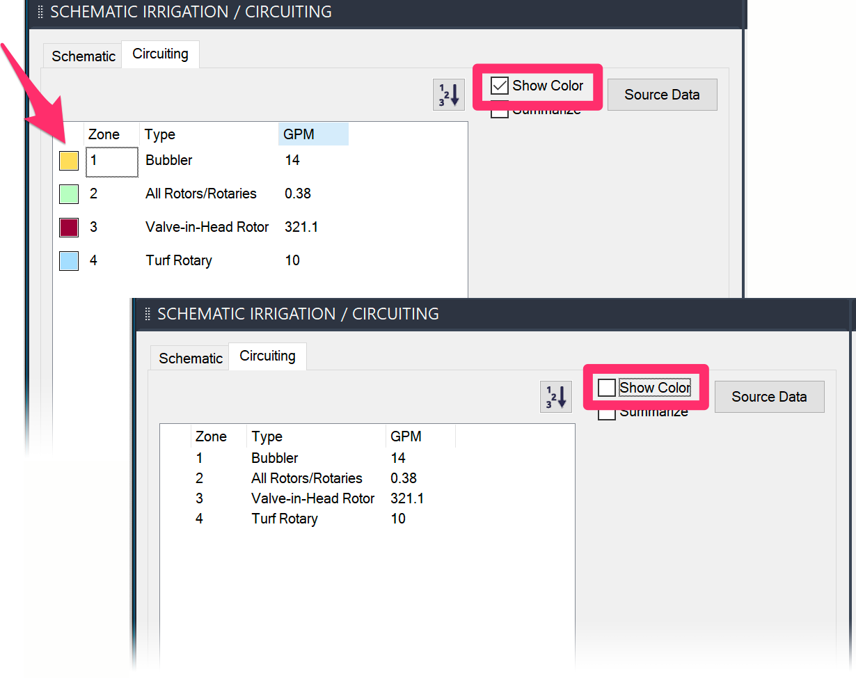
4. Show Color: Select this option to display the colors of your zones in the Circuiting Manager, or deselect it if you don't want to display the colors.
5. Summarize: Select this option to shorten your list of zones by grouping zones of the same head type together.
6. Use this button to configure and place a water source for your irrigation system using our Source Data tool.
7. New Zone: After selecting a head type at the top, click this button and draw a polyline fence around a group of heads. The zone number will automatically advance and will place that zone number along with the total flow for that group of heads within the zone. Each zone is created with a different color for clarity.
8. Edit the data assigned to a selected zone.
9. Delete a zone from both the list and your drawing by selecting it in the Circuiting Manager and clicking Delete.
10. Merge two or more existing zones into one larger zone. (The zones don't need to connect with each other in the drawing.)
11. Select a zone and click Locate to zoom find that zone in your drawing and zoom into it automatically.
12. The Total flow or GPM for a selected zone.
13. Click this Recalc button to ensure that all your zone calculations are up to date, including the flow total.
14. Head Tally: Calculate the flow of a group of heads without having to create a zone.
15. Uniformity: This feature automatically examines the layout of each head, determines when an area receives coverage from one or more heads, and color code those areas by how many heads have coverage in that area. For more information, see our Uniformity documentation.
16. Flow Total: Tally all head types you've placed into the drawing. The number will appear in the drawing.
17. Schedule: Create a Zone Schedule.
Creating New Circuiting Zones
Our Circuiting tool allows you to add up the flow of a specific group of heads in your design by selecting them one at a time, selecting a group with a polyline, or selecting and labeling a circuiting zone with a polyline.
To circuit properly, you'll first need to determine the maximum flow allowed by your point of connection (POC). The flow of each head grouping that makes up a circuit should not exceed the maximum allowable flow for the POC.
When you circuit heads, you're:
- Grouping similar heads together. Turf spray heads will never be grouped with shrub heads.
- Grouping similar plant materials together. Water-loving plants should not be grouped with drought-tolerant plants.
- Grouping similar exposures together. Shade areas should not be grouped with sunny areas.
- Grouping rotor types together. Different rotor models should not be grouped together.
- Grouping rotor arcs together. Most rotors are not matched precipitation, so group similar arc heads only on the same system
For this example, the maximum flow for each circuit is no greater than 65 gpm. The heads need to be circuited together in logical groupings that do not exceed this limit.
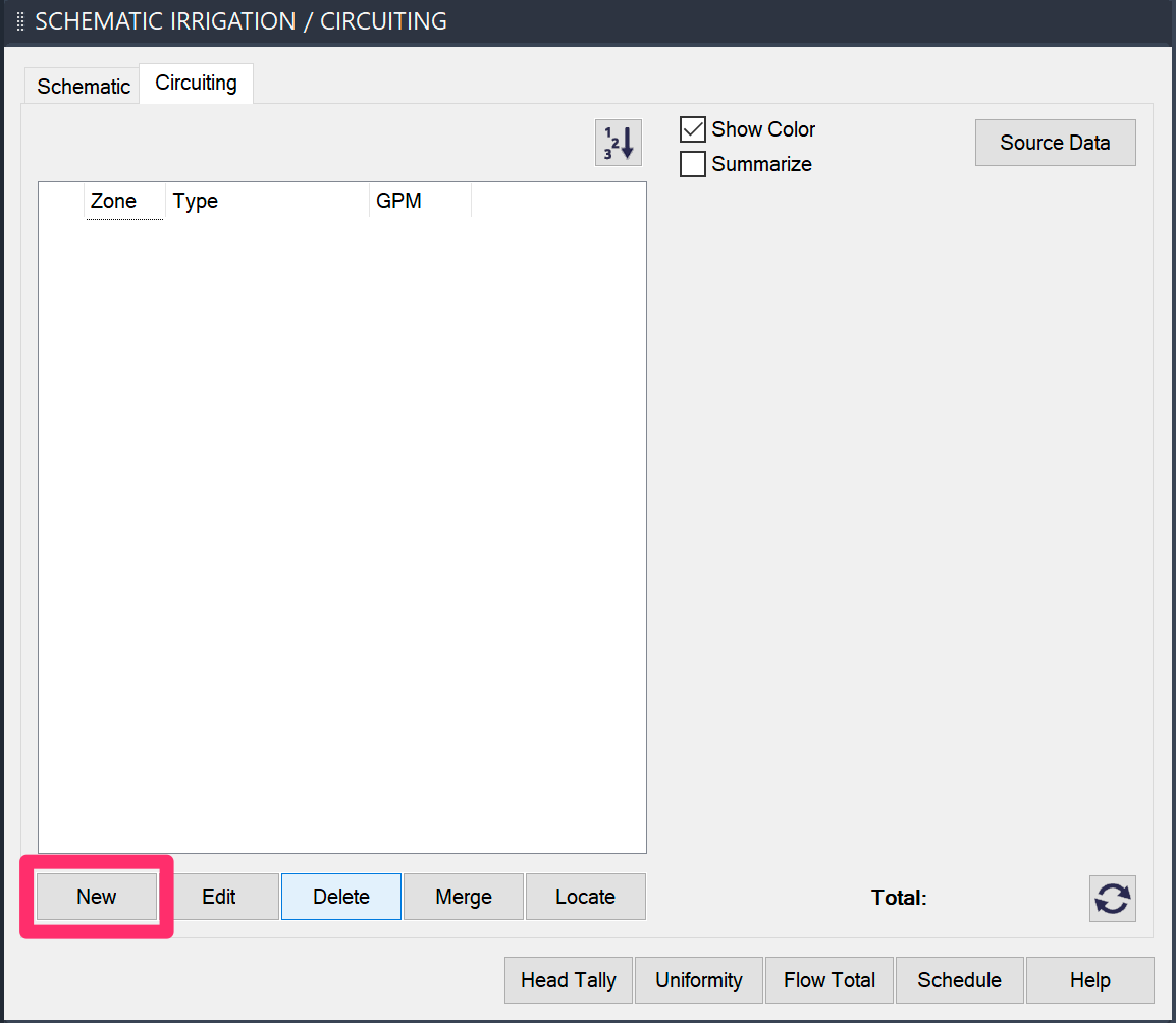
Open the Circuit tool and click New to begin creating a new zone.
You no longer need to pre-select your emitter type. You can just start adding zones as needed.
You'll be prompted First point, [Select]
You can now either:
- Draw a closed polyline around the equipment you want to include in your zone, or
- Press S to select an existing closed polyline to transform into a zone
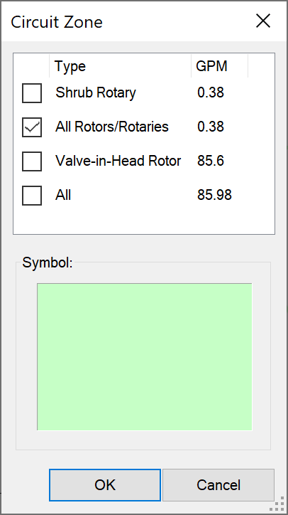
After you've drawn or selected your zone boundary, the Circuit Zone dialog box will open. The Circuiting tool will automatically determine the type(s) of heads included within the zone, and will list them here.
Select each head type you want to include in the zone. The zone's boundary will ignore any head types you do not select.
Click OK to create the zone.
After you've created a zone, it will be listed in the Circuiting Manager and assigned the next available number.
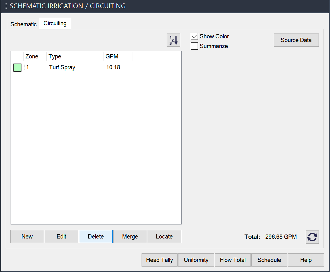
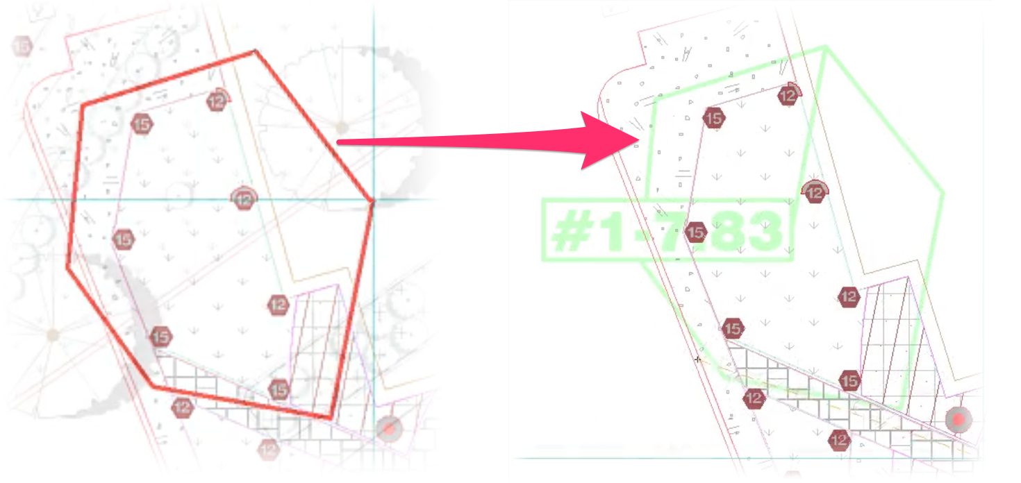
In this example, we've drawn a zone around a turf spray area. The zone is identified by its number (#1), and the zone number is followed by that zone's flow total (7.83 GPM).
Note that each zone's boundary acts as a crossing and will only count heads of the type(s) you selected when creating the zone that lie within the border area or intersect the bounding polyline.
The zone numbers (#1, #2, etc.) are arbitrary, and relate only to the order in which you've created your zones. To delete a zone, simply delete the polyline boundary and its text total. The next time you open the Circuiting manager, that zone number will be gone.
Notice that when you place a zone:
- The radius layer of the heads turns off to help clarify the drawing.
- While each zone polyline border is a different color, the borders are all on the layer LI-HEAD-ZONE. At any time you wish, turn off the zone layer using either the Layer dialog box or the Express Tools Turn Objects Layer Off button.
- The layer LI-HEAD-ZONE is a non-plot layer and will therefore not show up if you plot.
- The zone polyline border has a line weight of 0.40 mm. If you work in line colors and not lineweights, this function turns on the AutoCAD function Lineweight, indicated by the LWT button at the bottom of the screen. When finished with the zoning, you may want to turn off the LWT button if it's still on.
Editing Zones
To edit one of your zones, select it in the Circuiting Manager and click Edit.
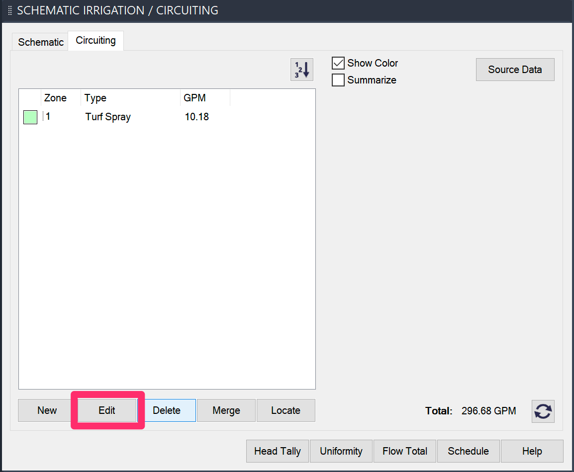

The Circuit Zone dialog box will open.
Here, you can select a different head type to be represented by the zone. You can also click the Symbol thumbnail to choose a different color for the zone.
Click OK to save any changes.
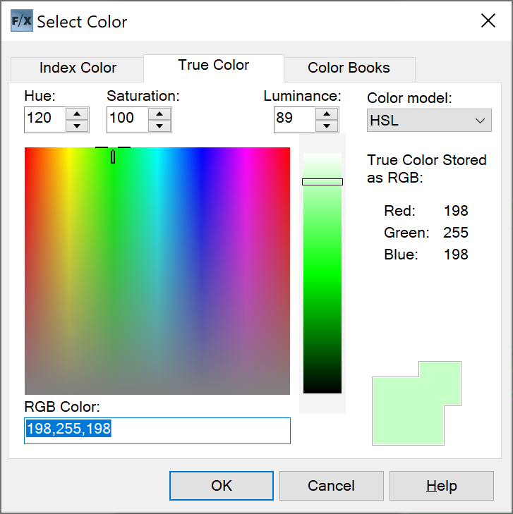
If you click the thumbnail to select a new color, the Select Color dialog box will open and you can select the color of your choice for the zone.
Merging Zones
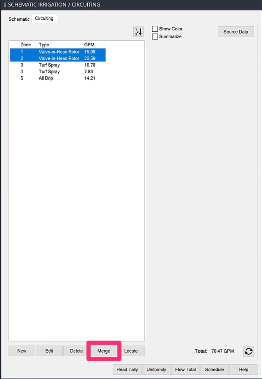
You have the following options for merging two or more existing zones into one:
- Select multiple zones in the Circuiting Manager and click Merge (as pictured in the example to the left), or
- Select one zone in the Circuiting Manager, click Merge, then select the other zone(s) you want to merge with it.
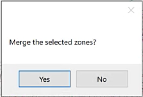
When asked Merge the selected zones? click Yes.
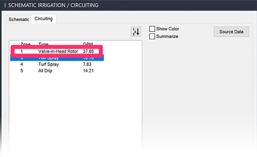
In either case, the zones you selected will be combined into a single zone.
Filtering Your List of Zones
You also have several options for filtering the list of zones in the Circuiting Manager.
Show Color
Select the Show Color option to display the color of each zone in the left column.
Deselect this option to hide the zone colors from view in the list.
Summarize
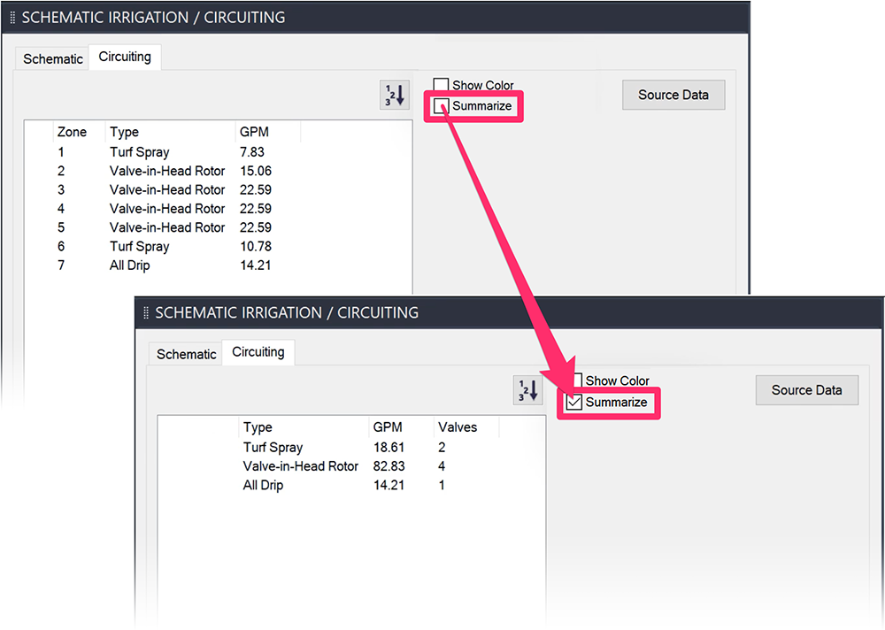
Select the Summarize option to shorten your list of zones by grouping all zones of each head type together.
Reorder Zones
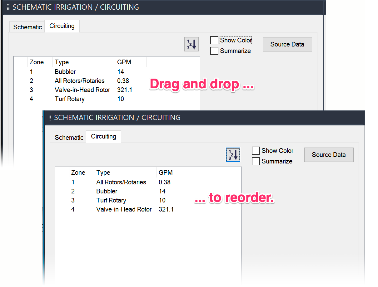
It's easy to reorder and renumber your zones. Just deselect the Show Color option, then drag and drop the zones in the list where you want them.
The zones will be renumbered according to their new order.
Renumber Zones
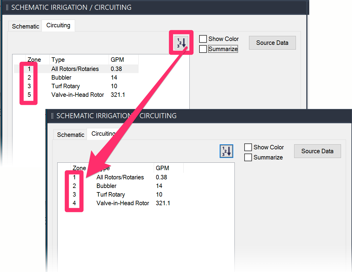
Deleting or reordering zones can sometimes result in gaps in your zone numbers.
To renumber your zones so their numbers are all sequential, click the Renumber (123) button.
Sort Zones by Column Data
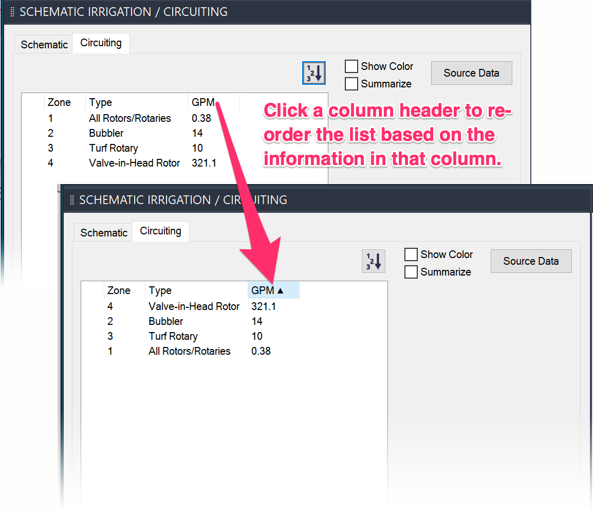
To sort your list of zones by the information in one of the columns, click the column header.
The list will reorder according to the data in that column. For example, you can order your list of zones according to their flow rates by clicking the GPM column header.
Head Tally
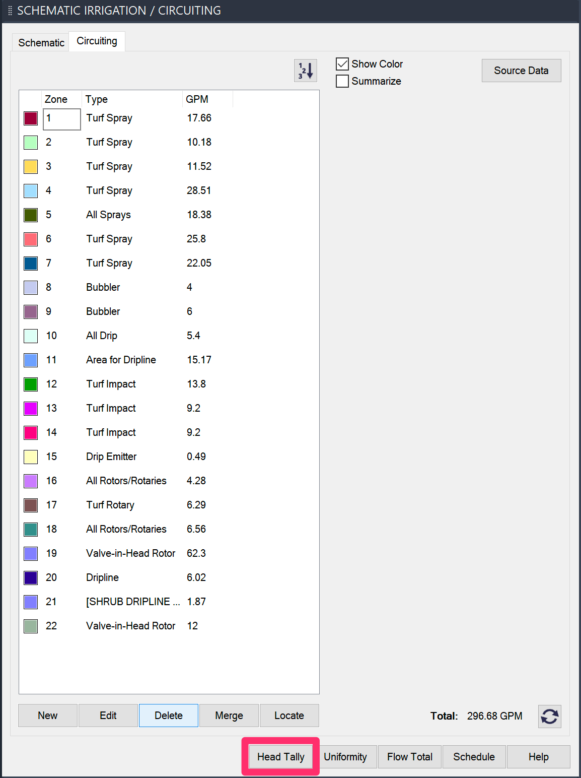
To tally the flow of multiple heads of the same type, click Head Tally.
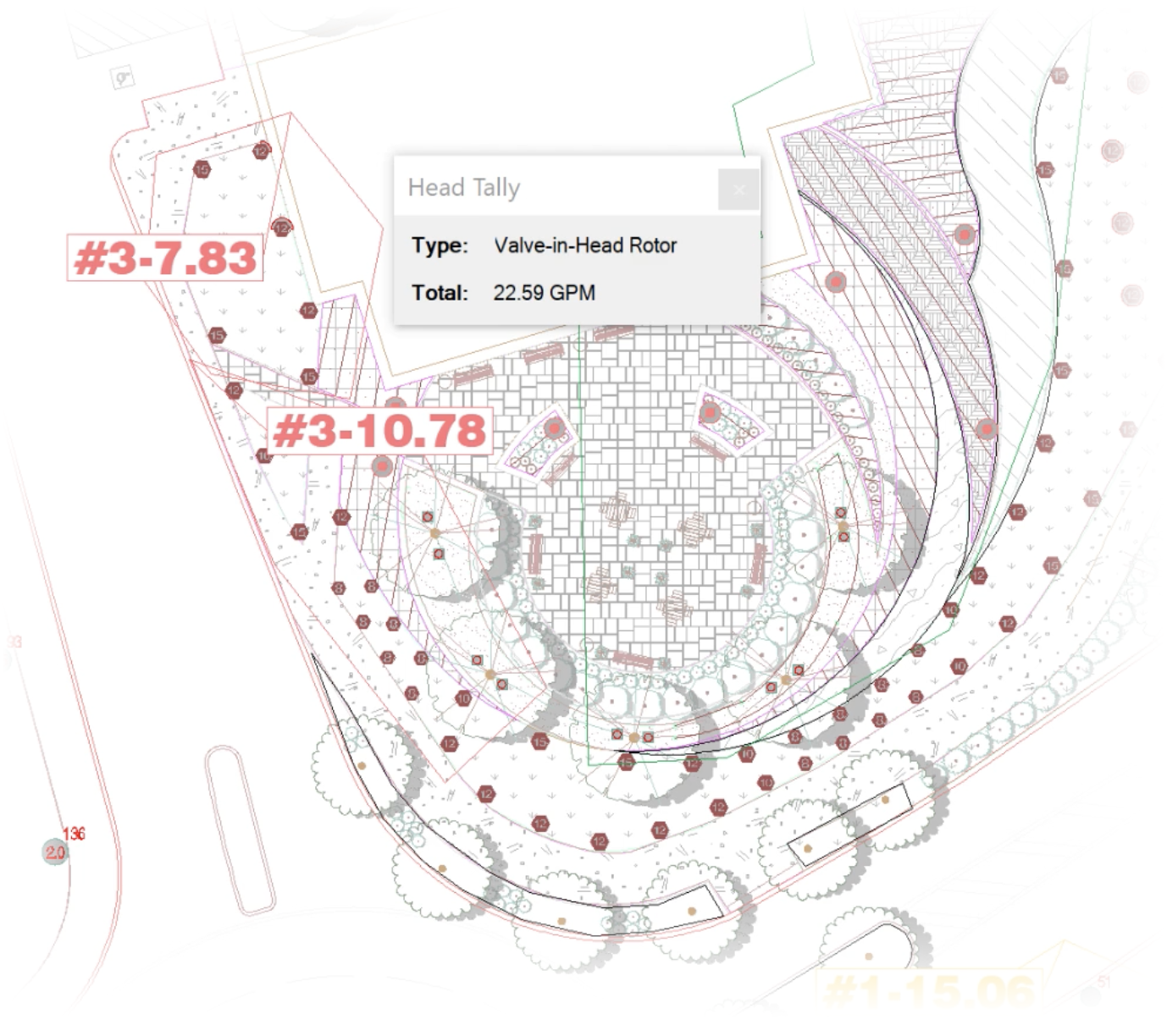
Select heads of the type you'd like to tally.
Each time you click a different head, a small dialog box will show the combined total flow for all the heads you've selected with the Head Tally tool active.
Flow Total
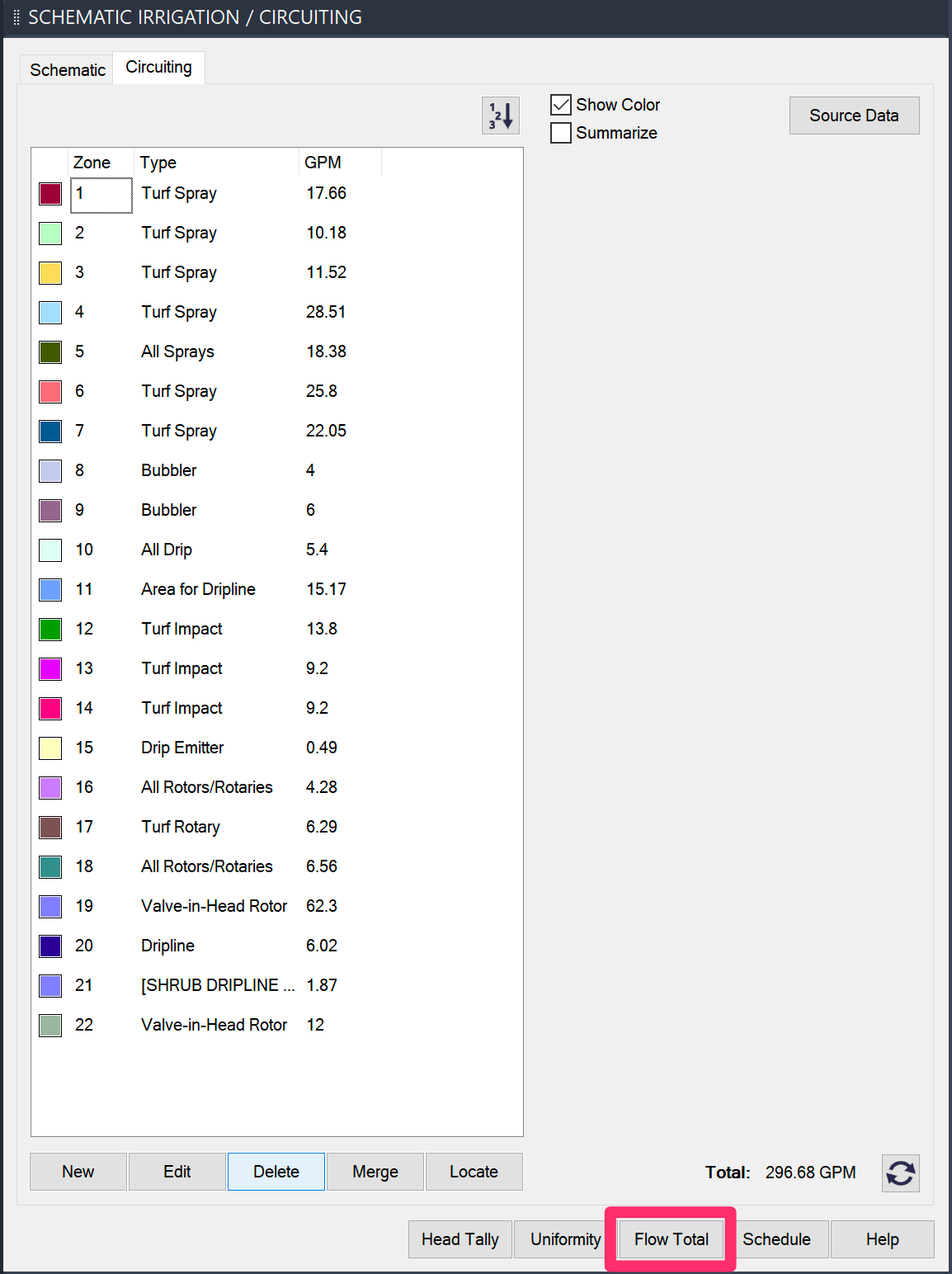
Our Flow Total tool counts the cumulative flow of the heads in your drawing, categorized by type, and then performs some basic calculations based upon the flow capabilities of your project's Source Data.
Click the Flow Total button in the Circuiting Manager to calculate a flow total.
The Command line will prompt you to select an Upper left corner. Click to place the flow total in your drawing.
The flow values will appear in your drawing as a schedule.

If your irrigation plan includes more than one water source, the valve numbers will be represented as a range. The actual number of valves used will likely vary, but this simple calculation can help you determine which controller will be necessary, or whether the system is too much for a single point of connection (POC).
Uniformity
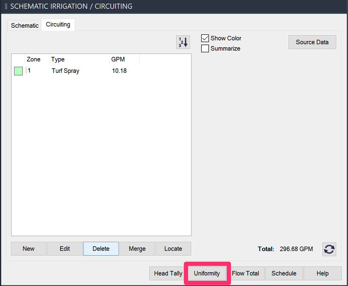
Our Uniformity tool provides a quick way to test the coverage provided by your head layout.
To open this tool, click Uniformity.
See our Uniformity documentation for more information and instructions.
Adding to an Existing Zone
You have some options for adding to an existing zone:
- To merge a zone with one or more additional existing zones – even zones that aren't adjacent to it – use the Merge feature.
- To create new portions of an existing zone that aren't contiguous with it, first create a new zone and draw it around the heads you want to include in the original zone. Then use the Merge feature to merge the original zone with the new zone(s) you created.
- To expand an existing zone, you can simply add to or expand its border.
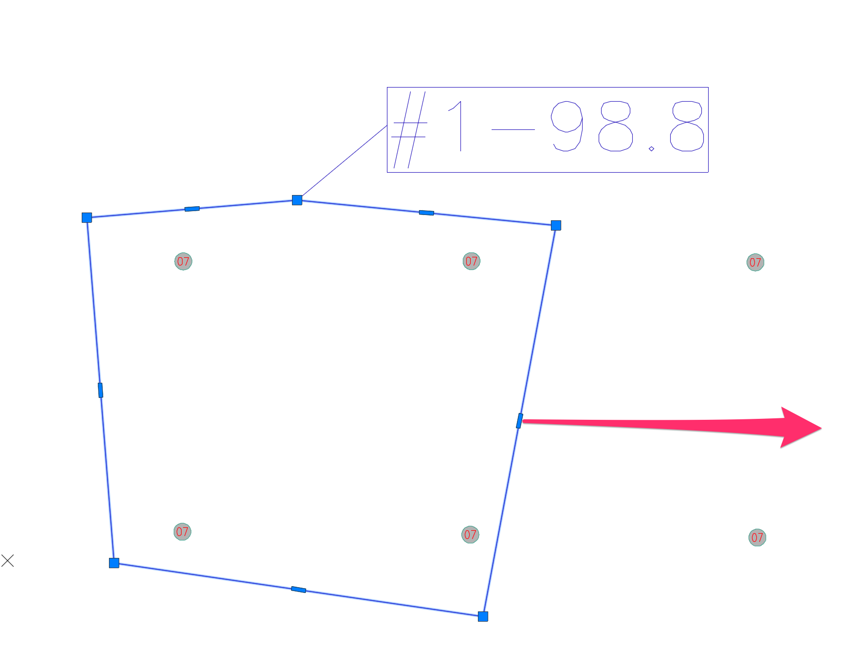
In this example, we'll expand an existing zone to include the two heads immediately to the right of it.
We'll select the zone boundary, grab a vertex, and drag it to the right so the boundary includes the two extra heads.
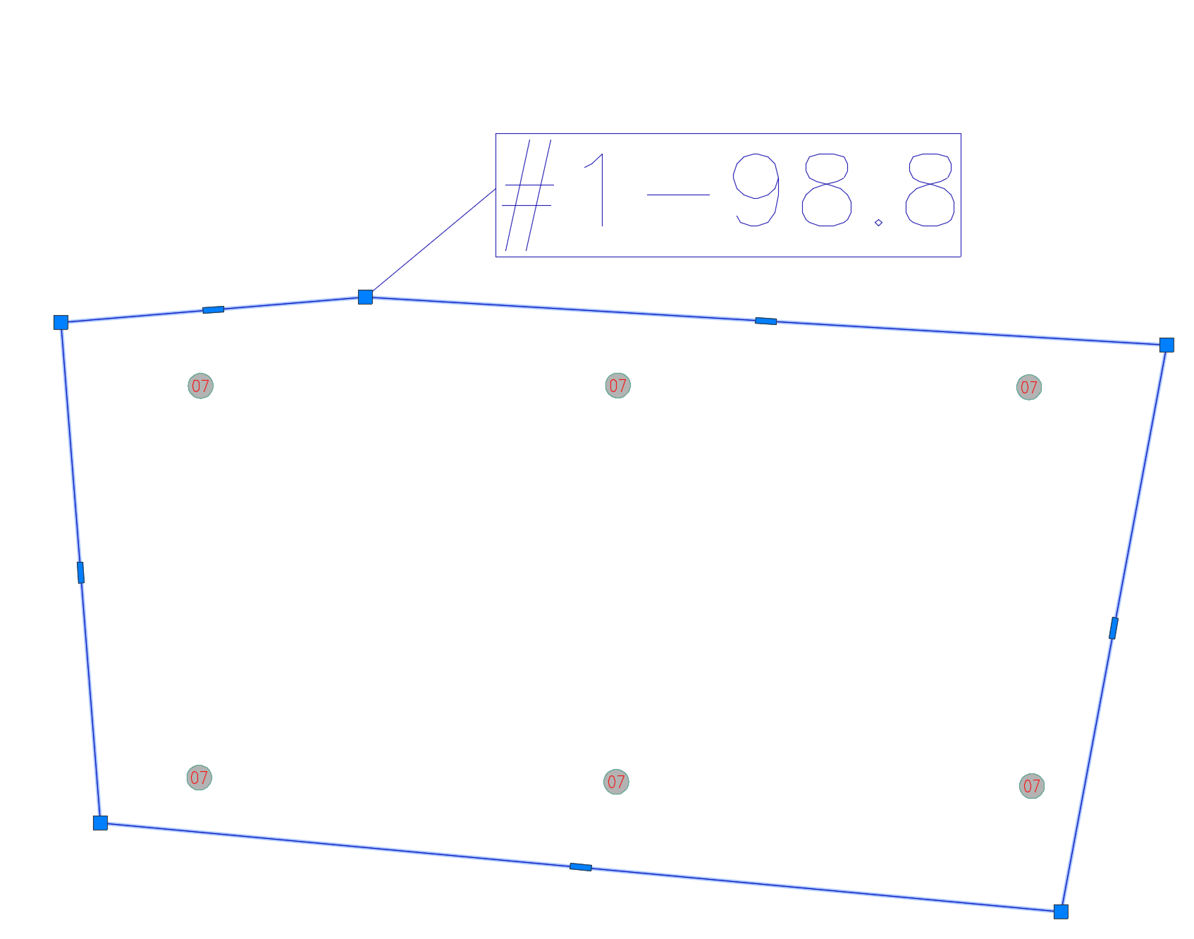
The zone boundary now includes the two additional heads.
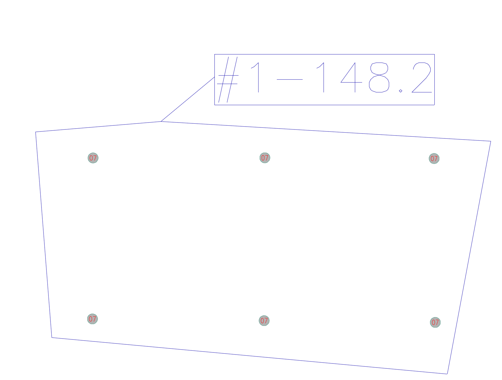
Note that the zone's flow total will remain the same until we click the Recalc button in the Circuiting Manager.
Clicking Recalc updates the flow total to include the new heads.

Clicking Recalc also updates the zone's flow total in its MLeader callout.
Placing a Zone Schedule
To place a schedule of the zones you've created, click the Schedule button in the Circuiting Manager.
The Zone Schedule is now powered by our Reference Notes (RefNotes) Schedule feature, which we improved with some major updates as of August 2024. More information
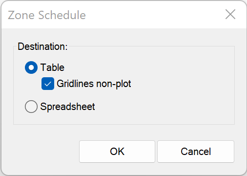
The Destination section of the Zone Schedule dialog box includes several options for how and where you want to place or send your schedule:
- Table: Place the schedule in your drawing as a table.
- Gridlines non-plot: Check this option if you want the lines separating the table cells to be non-plot. Uncheck this option if you want the table lines to plot.
We've replaced the Drawing and Table options with this single Table option and the Gridlines non-plot checkbox. If you select Gridlines non-plot, the schedule will place with gray gridlines that will not show up when you plot your drawing (essentially the same as the former Drawing option). Deselecting this option will result in a schedule placing as a table with gridlines set to plot (essentially the same as the original Table option). This updated system allows you to edit your schedules much more easily.
- Spreadsheet: Export the schedule to a spreadsheet program such as MS Excel.
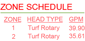
The example to the right shows a schedule that includes two zones, placed directly in the drawing.
The schedule shows the flow (GPM) calculations for both zones.
"No Flow Total for Selected Head Type" Message
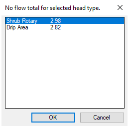
If you receive the message No flow total for selected head type, it means you've selected a spray type for a zone, and that spray type doesn't exist.
If so, you simply need to select the correct spray type.
Undocking the Circuiting Manager
The Circuiting Manager is a docked palette by default. To find out how to undock it, see our docking and undocking the Irrigation Manager and Schematic Irrigation / Circuiting palette documentation.
Related Webinars
- Getting Started with Irrigation F/X: This tour and tutorial will help you make the most of everything Irrigation F/X has to offer. We start with the fundamentals, such as how to set up your projects and Preferences, before diving into our collection of time-saving irrigation design tools. (59 min)
- Irrigation for Beginners: We'll show how to navigate through the Irrigation ribbon and build a familiarity with our conceptual-level tools. You'll also learn the basics of adding equipment to a project, placing, piping, sizing, and scheduling. (1 hr 45 min)
- Irrigation Tools – What You Need to Know: We'll show you the ins and outs of basic irrigation setup using our software. You'll also learn the essentials of placing equipment such as drip, sprays, and rotors. (1 hr 6 min)
- Start to Finish Basics of Irrigation Design: This webinar will help give you an understanding of how to specify the proper equipment, talk about important concepts of irrigation design, and create a complete irrigation plan from start to finish. (1 hr 31 min)
- Irrigation Tips & Tricks: We'll show you some advanced tools you may or may not know about. You'll also learn techniques and best practices that will help speed up your workflow. (1 hr 3 min)
- Existing Irrigation: Learn the techniques, tools, and tricks you'll need to expand an existing system, including how to use a pipe cap to account for existing flow and add new valves to an existing mainline. (56 min)
- Advanced Irrigation Troubleshooting: Learn to think like a Land F/X irrigation troubleshooter. We'll show you why your symbols don't match, why you would see the message "Error accessing equipment data" (and how to fix these issues, as well as tips on pressure losses and precip rates, pipe caps, system monitors, and flow zones. (1 hr 3 min)
Troubleshooting
Issue: You attempted to Zoom to Extents, and the command canceled out and deleted your Zones
Issue: Error: Zone text has been edited when trying to use the Circuit tool
Issue: Your Circuit zones don't match the flow totals in your Valve Callouts


