Colorize Zones & Drip Hatches
Quick video
Once you've laid out and piped to your irrigation heads, you can produce a colorized version of your irrigation design. This colorized version will identify the stations you've created.
You can use this colorized version of your design in creating an as-built drawing or controller chart. You can also use it to communicate your design intent to site owners or contractors.
Our colorization feature now adds color to drip hatches – including drip emitter areas and dripline areas.
Colorization Overview
We recommend putting some thought into what type of drawing you want to produce with your colorized zones and drip hatches. If you want a clear communication tool printed at the full size of the plan, you may want to leave the drawing much as it is. If you want to accent the colorization dramatically, you may want to half tone the plan so the colors stand out. You might decide to turn off unnecessary layers in order to communicate some intent clearly.
Want to colorize only one zone/station? Use the Colorize option in our Highlight Station tool.
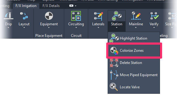
Open Colorize Zones:

F/X Irrigation ribbon, Colorize Zones flyout
or type FX_COLORZONES in the Command line

F/X Irrigation menu, Colorize Zones option
Colorize Zones is also built into the process of creating a Valve Schedule:
Check the Colorize Zones box when creating a Valve Schedule.

When you select Colorize Zones, the zones (stations) and drip hatches in your drawing will be highlighted with a color and the Command line will prompt Upper left corner for you to place the Valve Schedule.
If you want, you can go ahead and place the Valve Schedule. Because your drawing will already be colorized at this point, you can also choose to cancel the Valve Schedule by pressing ESC.
Type LAYER in the Command line and press Enter to open the Layer Properties Manager.
Find the layer LI-PIPE-HILT and change the Lineweight and Plot settings.
- Make the Lineweight setting a thicker amount than the default, which is 0.50mm (0.020”). Try a thicker line, then and do a print/plot preview; repeat these steps until you achieve the look you want. For example, try 2.0mm (0.080”).
- Check the printer symbol on the Plot setting to change between non-plot and plot.

The layer LI-PIPE-HILT with the Lineweight set to 2.00mm and the Plot set to plot
Now look at the drawing in a Paper Space Layout tab and do a Plot Preview to see how it will look. If the preview looks good, you're ready to plot.
Here's an example of an irrigation plan with colorized zones (stations):

If your plan includes drip emitter areas or dripline areas, the hatches representing those areas will also be colorized.
We recommend saving this revised drawing with a new name.
Selecting a Single Valve
You can also choose to select a single valve to colorize that valve zone. Your color choice for that zone will be saved with that valve.
Turning Colorization Off
You may want to turn off the colorization feature at some point – whether you've seen what you need to see or you've simply had the Colorize Zones feature checked mistakenly when running a Valve Schedule.
We put the colorized zones and drip hatches on their own layer for this very purpose: So you can turn on and off when needed. Simply use the LAYFRZ command or go to your Layers Property Manager and turn the layer on/off as needed. For more information, see our Freezing/Thawing a Layer and Turning a Layer On/Off instructions.
Troubleshooting
Issue: Colors are displaying incorrectly in Model Space


