Place Area for Drip Emitters or Drip Spray
Quick video
- Place Area for Drip Emitters or Drip Spray: Overview
- Important: Avoid Arcs in Your Drip Area Boundaries
- Placing Individual Emitters
- Changing the Hatch Symbols for Areas for Drip Emitters in Your Projects and Drawings
- Piping to Drip Emitter Areas
- Having a Hatch Issue? Download Our Updated Hatch Patterns Manually
- Related Webinars
- Troubleshooting
An Area for Drip Emitters is applicable for emitters, bubblers, popups, and multi-outlet emitters. These contiguous systems are intended to serve entire planted areas where each plant will receive drip emitters or bubblers.
Applicable for emitters, bubblers, popups, and multi-outlet emitters, an Area for Drip Emitters is intended for entire planted areas where each plant will receive drip emitters or bubblers. When installed, these areas will consist of above-grade 1/2-inch poly drip tubing with single-outlet emitters to each plant, either directly connected to the drip tubing or attached to the tubing with 1/4-inch distribution tubing to drip stakes.
Areas for Drip Spray – a subset of Areas for Drip Emitters – apply to planted areas that will receive virtual head-to-head coverage of drip spray. These areas also consist of above-grade 1/2-inch poly drip tubing with spray outlet emitters directly on the tubing or attached to the tubing with 1/4-inch distribution tubing to drip stakes.
Areas for Drip Emitters and Drip Spray are represented by a hatch pattern and a dashed border outline.
The default install does not include all symbols, but many of them will download on demand. If you go to place a head, the symbol should download as necessary.
You can also have the system download all irrigation symbols from the Check for Updates feature if you would like.
A Note on Curved Drip Area Polylines: When you place a drip area – whether for drip emitters or driplines – you are placing a hatch within a closed polyline area. Drip areas treat curved polylines uniquely, specifically because drip areas need to determine whether a pipe endpoint is within the area where you place them. Because the necessary math becomes wildly more complicated with curved edges, the system has to decurve boundary polylines when using them as drip areas. This is precisely why, when you place a drip area within a boundary that includes one or more curved polylines, the curved line will morph into a series of contiguous segments when you place the hatch.
Placing an Area for Drip Emitters or Drip Spray: Overview
Note that Area for Drip Emitters tool is only compatible with project plant symbols and hatches. If you're using Concept plants, you'll need to place them as project plants prior to sizing any valves connected to drip emitter areas.
Drip single-outlet emitters are intended for use with an above-grade drip tubing system.
You can apply these emission devices directly to the 1/2-inch drip tubing, or to the tubing with 1/4-inch distribution tubing to drip stakes.
Drip emitters are designed to look for plants in your Xrefs – not in the current drawing. When the software runs through the project to determine the number of plants for which it needs to calculate flow, it will look through the current drawing first. If it finds any reference to plants, it will stop looking. If it does not find any plants, it will then move on to the Xrefs. Therefore, you should always create your drip plan in a separate .dwg from your planting plan and then Xref the planting plan into your drip design. If the drawing containing your drip plan also contains plants, you will need to find and remove those plants. Find out how.
To create the bounding polyline for an Area for Drip Emitters, draw a polyline on any layer around the areas that are to be irrigated with a drip tubing system. You can also wait to draw this polyline until when you are actually placing the area.
Open the Area for Dripline tool:
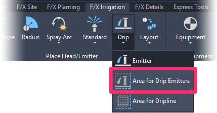
F/X Irrigation ribbon, Area for Drip Emitters flyout

F/X Irrigation menu, Area for Drip Emitters option
or type FX_PlaceDripEmitterArea in the Command line
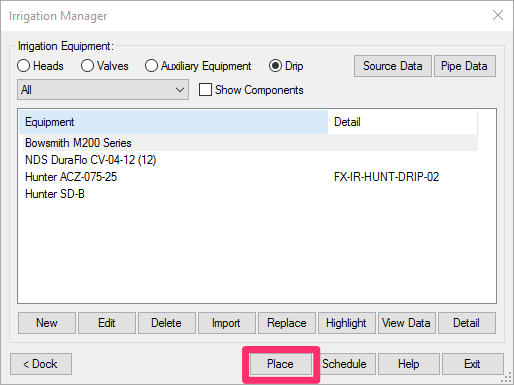
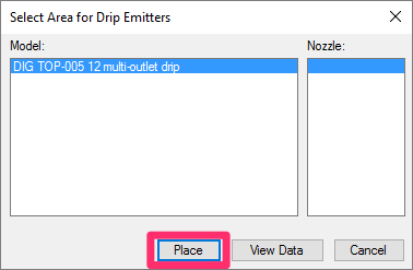
The Select Dripline dialog box will open. This dialog box lists all driplines you've added to your project. Select a dripline, then click Place.
If you used the Irrigation Manager to place your Area for Drip Emitters, you'll skip this step.
The cursor will turn into a pickbox, and the Command line will prompt you to Select polyline to hatch, [Draw Multiple].
You can now place your Area for Drip Emitters in an existing closed polyline area or:
- Begin drawing a closed polyline area. Your hatch will be applied to this area once you close it.
- Type M for Multiple: This option allows you to select one or more closed polyline areas within your hatch boundary and exclude them from the hatch.
If you type M for "Multiple," the cursor will change to a pickbox that will allow you to make a polyline selection. More information >
Selecting an Existing Polyline Boundary
Back in your drawing, select a closed polyline that represents the area intended for drip outlet emitters.


The polyline border will change to a dashed drip border area line, and a hatch pattern reflecting the selected drip emitters will be inserted in the area.
If you're having issues with a drip emitter area (for example, a valve is failing to acknowledge one or more plants), you'll need to troubleshoot the drip emitter area. Type FXDEBUG in the Command line, then use the Highlight Station tool to select the troublesome valve. The system will output some additional information to the Command line. You can then press the F2 key to view this information, which should allow you to determine the specific problem.
Do not try to overlap tree and shrub areas. The software – and anyone looking at your plan – will be unable to distinguish between them, and it will cause issues with piping to your emitters.
Drawing a Hatch Boundary "On the Fly"
If you haven't yet drawn a polyline boundary for your Area for Drip Emitters, you can now do so "on the fly" after selecting the type of irrigation zone to place.
When you go to place an area, the Command line will prompt you to Select polyline or interior point to hatch, [Draw Multiple].
Start drawing your closed polyline. Once you close it, the hatched area will appear within the polyline boundary.
In previous versions, drawing your hatch boundary on the fly would require you to first type D for Draw. We've now built in the ability to simply start drawing your closed polyline. As long as the first point you select isn't an existing polyline, the Draw command will be fired automatically.
This feature works with all of our default hatch types, including:
Excluding Interior Objects from a Drip Emitter Area Hatch (Multiple Option)
In many cases, areas where you want to place drip emitters will contain objects that you want to exclude from the drip emitter hatch – such as benches, paths, or boulders.
To exclude these objects from the hatch, type M when placing the dripline area.
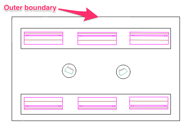
The cursor will turn into a pickbox, and you'll be prompted to Select outer boundary.
Use the pickbox to select the outer boundary of the area where you want to place the drip emitters.
You'll then be prompted to Select interior boundary.
Use the pickbox to select any interior objects you want to exclude from the hatch. You can just keep clicking until you've selected all the objects you want to exclude.
When finished selecting interior objects, right-click or press Enter.
In some cases, you may need to draw circles or rectangles around objects you want to exclude.
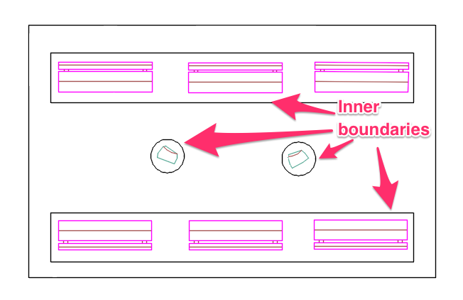
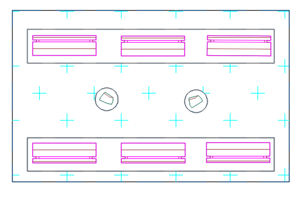
Once you've right-clicked or pressed Enter, the hatch will be placed and will exclude all the objects you selected.
Cannot process multiple boundaries because the outer polyline includes loops.
Seeing this error message when trying to use the Multiple option while placing a drip area hatch?

Excluding Trees from a Drip Emitter Hatch
You have a couple of options for excluding trees from a drip emitter hatch. For information and instructions, see our article on excluding trees from a drip emitter area.
Why You Can Only Add One Drip Emitter Area Type to Each Project
We only allow a single drip emitter area type in each project. This restriction is necessary because trees and shrubs tend to be co-mingled, but only a single hatch can realistically be placed in those areas. One option might be to have a different symbol for the tree valves, but we opted against this possibility because of possible confusion if the contractore were to see these different valves both serving a hatched area, likely accompanied by some note off to the side somehow attempting to delineate which valve is to connect to which emitters.
Therefore, your best bet in this case is to have drip emitter areas only serve the shrubs, and then connect the tree valves to their individual emitters – you are welcome to select poly as an additional pipe class to use in this manner. More commonly, trees are served by PVC-piped bubblers, which would also be our recommendation.
Important: Avoid Arcs in Your Drip Area Boundaries
It's extremely important to avoid using arcs in your drip area boundaries. Here's why:
For drip areas, we need to be able to determine whether a point lies within any given area. This determination will in turn allow the software to see whether a freestanding emitter is part of that drip area, as well as for flush valves and pipe transition points. Because running the pipe sizing can require dozens and even hundreds of these crosschecks, all this calculation has to happen extremely quickly. So long story short: If the boundary path consists of all straight lines, it can be accomplished with a simple operation. If arcs were allowed, the system would need to convert each arc to a series of straight lines – each and every time. Or, failing that, it would need to convert every object to a 3D Region object, and use the Region modeler routines. But again, all of those are quite involved and tax the computer, as opposed to simply converting any arcs to straight lines when the drip area is initially placed.
Placing Individual Emitters
If you want to place an individual emitter for each plant, you have a couple of options:
Option 1: Place Individual Emitters With No Area
If you want, you can simply place individual emitters without a drip area. You can then select a second lateral pipe category (such as polyethylene) using our Pipe Data tool and then use that second pipe category to connect to each emitter.
Option 2: Place Individual Emitters Within a Custom Drip Area
You can also place individual emitters within a "custom" drip area.
When adding a drip area to your project, select the Custom option when selecting a manufacturer.
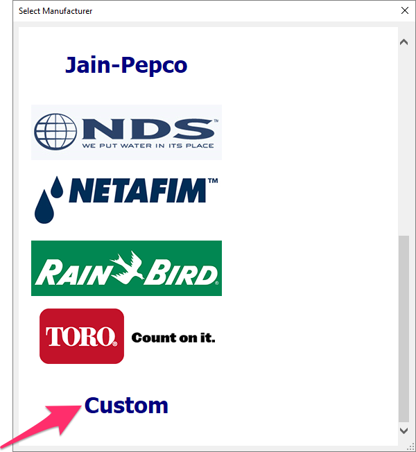
Then, when you place the drip area in your drawing, you can use the drip area to designate the region that will be served by poly tubing – but still place the individual emitters. Because the emitters are placed within the drip area, you won't have to pipe to each one.
Changing the Hatch Symbols for Areas for Drip Emitters in Your Projects and Drawings
If you've already added a particular Area for Drip Emitters to your project – even if you've already placed it in a drawing – you may want to change its hatch to another one of our default hatches, or a version you've created. See our documentation on changing symbols for Areas for Dripline and Drip Emitters.
Piping to Drip Emitter Areas
After placing your drip emitter areas, you'll need to take some specific considerations into account when piping to them. See our PIping to Drip Areas documentation.
Having a Hatch Issue? Download Our Updated Hatch Patterns Manually
Are you experiencing any of the following issues with your drip area hatches?
- Hatches looking fragmented or broken apart
- Hatches with scales that are too large or too dense
- Hatches that place blank or empty
- Hatches that are not appearing in schedules
- File size bloating
If so, follow our steps to download our updated hatch patterns manually.
Related Webinars
- Irrigation for Beginners: We'll show how to navigate through the Irrigation ribbon and build a familiarity with our conceptual-level tools. You'll also learn the basics of adding equipment to a project, placing, piping, sizing, and scheduling. (1 hr 45 min)
- Designing with Drip: Learn to use drip irrigation, from placing drip rings, bubblers, single emitters, emitters by area, and dripline by area all the way to zoning and piping. (1 hr 3 min)
- Drip Irrigation: We’ll go through the entire process – from placing drip rings, bubblers, single emitters, emitters by area, and dripline by area to zoning and piping. (1 hr 5 min)
- Irrigation Tools – What You Need to Know: We'll show you the ins and outs of basic irrigation setup using our software, including how to add drip, sprays, and rotors to a project. (1 hr 6 min)
- How The Manufacturer Connection Works: The Manufacturer Connection is the relationship between the designer and manufacturer that Land F/X has used to separate ourselves from other design software programs. Learn how it helps you spec equipment for irrigation designs. (53 min)
Troubleshooting
Issue: An Area for Drip Emitters or Drip Spray is showing GPM (0 flow) or is not reading plants
Issue: Your drip hatches are not showing up in Paper Space
Issue: You are unable to pipe or connect to an Area for Drip Emitters
Issue: High flow (GPM) calculated in your drip valves
Issue: Error: "Unhandled exception in dcl-slideview-load ARX" when placing areas for drip emitters
Issue: The drip tubing calculations are incorrect (too high) in an Area for Dripline
Issue: You need to remove the hatch from internal objects within a drip area
Issue: Drip emitter areas in your drawing are showing the incorrect emitter quantity or flow rate
Issue: Your drip hatches are showing up incorrectly, or as random lines or solid colors
Issue: A placed drip area hatch looks fragmented or isn't joined like it should be
Issue: A placed drip area hatch looks different from its thumbnail preview slide in the Hatch dialog box
Having an issue with placing individual emitters? See our Place Drip Emitters Troubleshooting section.


