Lighting Manager: Adding and Placing Lighting Equipment
Quick video
- Lighting Overview
- Adding New Equipment
- Placing Equipment
- Placing Fixtures, Auxiliary Equipment, and Power Equipment
- Placing Wire
- Lighting Equipment and Work Areas
- Editing Lighting Equipment
- Creating Circuits, or Zones
- Generating a Lighting Schedule
- Labeling Equipment
- Photometric Data Via IES File Compatibility
- Lamp Color & Color Temperature
- Importing Lighting Equipment from a Template or Project
- Error Checking Your Lighting Plan (Verify Wiring)
- Edit our Lighting Symbols, or Add Your Own
- Related Webinars
- Troubleshooting
We offer a dedicated tool for adding and placing lighting equipment in CAD. Use our Lighting Manager to specify and place specific types and brands of lights, then create a lighting schedule to show costs, wattage, and other details.
Lighting equipment is now compatible with our Land F/X 3D connection!
Our 3D Connection makes it possible to send your designs from CAD to 3D (SketchUp, Rhino, and Revit) and back again. And now it's compatible with lighting equipment. For more information on sending your lighting plans between CAD and SketchUp, Revit, or Rhino, see our 3D Connection documentation.
Lighting Took the Prize at 2019 IA!
Our updated landscape lighting functionality took home first prize in the New Product Contest, Landscape Lighting category, at Irrigation Show 2019, put on by the Irrigation Association (IA).
Lighting Overview
Open our Lighting tool:
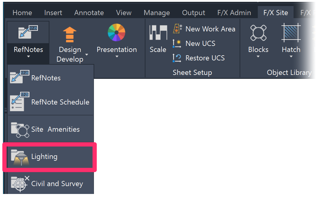
F/X Site ribbon, Lighting flyout
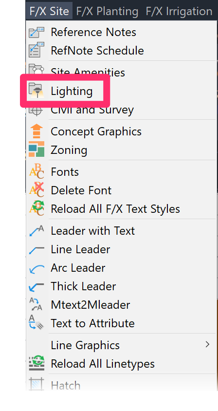
F/X Site menu, Lighting option
or type FX_Lighting_Manager in the Command line
The Lighting Manager will open.
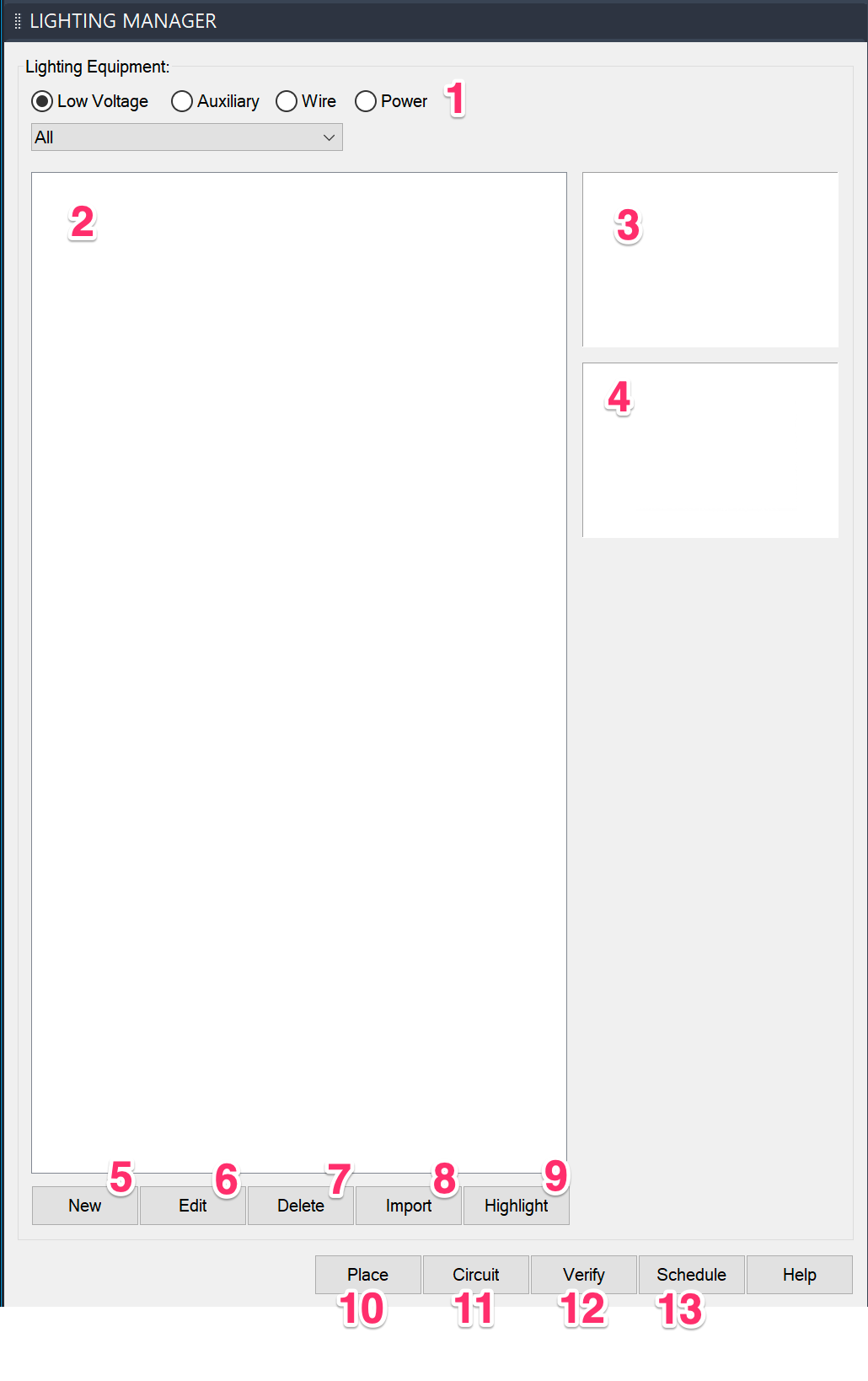
1. Select a type of equipment to add to your project.
2. Equipment you add to your project will be listed in this area. (Note: This area will be blank until you add lighting fixtures to the current project.)
3. The symbol assigned to a selected component will appear here.
4. The photo assigned to a selected component will appear here. You'll be able to place the photo in your drawing using our Photo Callout tool.
5. Add a new lighting component to your project.
6. Edit a lighting component you've added to your project.
7. Delete a lighting component from your project.
8. Import lighting equipment from another project or template.
9. To locate a placed lighting component in your drawing, select it from the menu and click Highlight. You’ll be taken right to that component in your drawing.
10. Place a lighting component in your drawing.
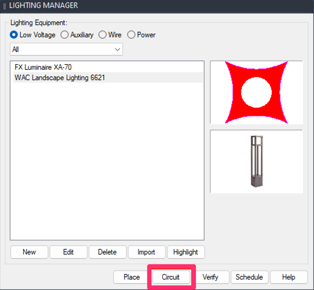
11. Use the Circuit button to define circuits, or zones, in your lighting plan.
12. Use the Verify button to error check the lighting equipment in your drawing.
13. Place a schedule of the lighting equipment you've used in a project.
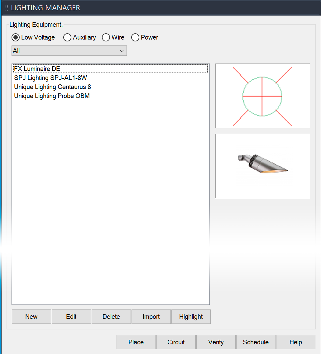
Here's what the Lighting Manager looks like once you've added equipment to your project:
Adding New Equipment
Select a type of equipment to add to your project (example: Low Voltage to add a lighting fixture), then click New.

Adding Low-Voltage Fixtures
Select the Low Voltage option (as pictured above) to add a lighting fixture to your project.
The Select Manufacturer dialog box will open.
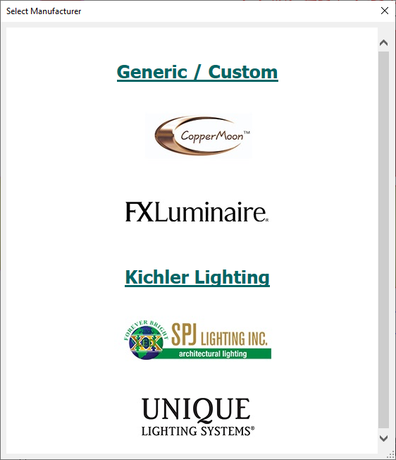
Here, you can either:
- Select a manufacturer to specify a fixture from that manufacturer, including reviewing that manufacturer's product line and unique specifications, or ...
- Select Generic/Custom to specify a generic or custom fixture.
Quick video
Adding Fixtures from Manufacturers
Click the logo of the manufacturer whose equipment you want to see.
The New Light Fixture dialog box will open. Here, you can access the lighting equipment available from the selected manufacturer in our database.
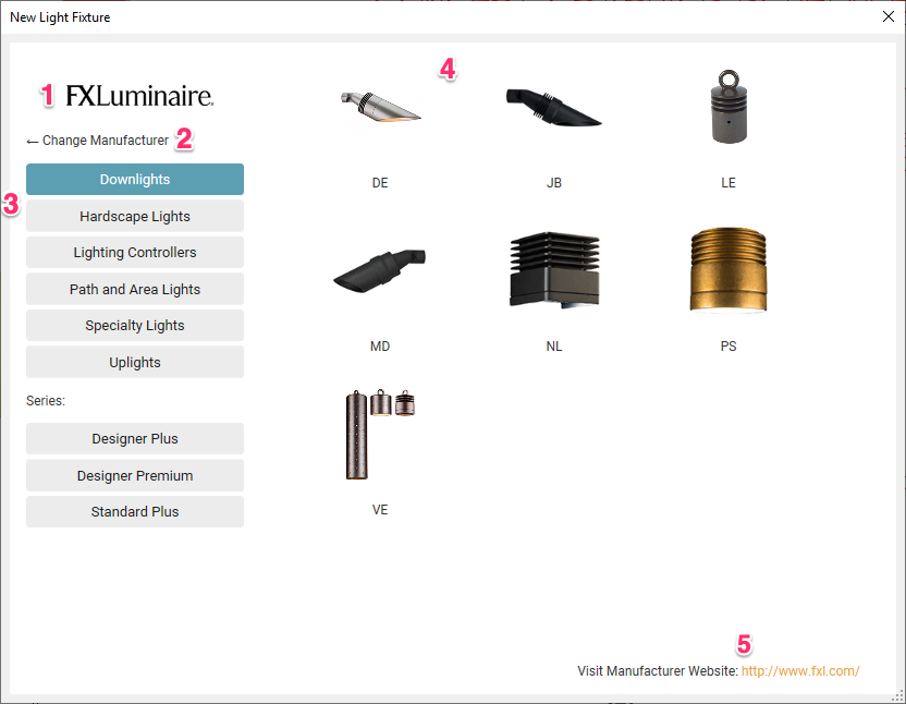
1. The selected manufacturer's logo.
2. Click this link to return to the previous dialog box and select a different manufacturer.
3. This list shows all equipment types available from the manufacturer in our database. Click an equipment type to select it.
4. Thumbnail images of all models within the selected equipment type. Click a thumbnail to select that model
5. Click this link to visit the selected manufacturer's website, browse the manufacturer's catalog, and learn more about the manufacturer.
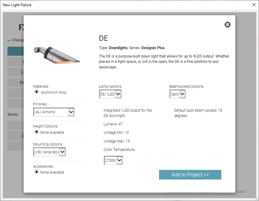
If you click one of the thumbnail images for a component, you'll see a dialog box specifically for that component, where you can configure a number of options including materials, lamp options, finishes, and more.
Click Add to project to add the component to your project.
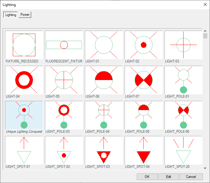
The Lighting dialog box will open.
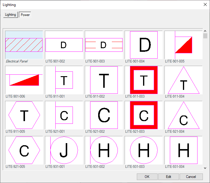
Select a symbol to represent the selected equipment, then click OK.
The New Light Fixture dialog box will open.
Here, you can review all the data assigned to the equipment.
1. The model name of the selected component.
2. The Note field will often be populated with manufacturer information about the component. Add to it if you want.
3. The two-letter code of the selected component.
4. Replace Fixture: Click this button to select a different fixture.
5. Assign a per-unit Cost to the selected fixture.
6. Assign a detail to the selected fixture, or remove a detail association from the fixture.
7. Use these menus to configure options such as lamp type and beamspread.
8. Thumbnail image for the symbol currently assigned to the selected fixture. Click here to select a new symbol.

9. Thumbnail image for the photo currently assigned to the selected component. Click here to browse to and select a new photo. You'll be able to place the photo in your drawing using our Photo Callout tool.
10. Additional options to configure, including material, finish, and mounting select.
11. Open the manufacturer's website to view data associated with the selected fixture model.

The model you specified will be listed in the Lighting Manager.
Adding Generic Fixtures
To add generic lighting equipment to your project, click the New button in the Lighting Manager.

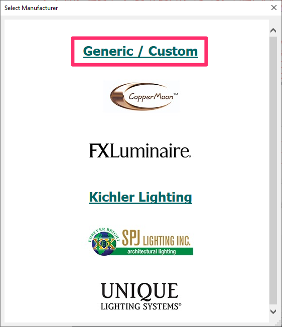
Scroll down to and select the Generic/Custom option in the Select Manufacturer dialog box.
The Lighting dialog box will open.
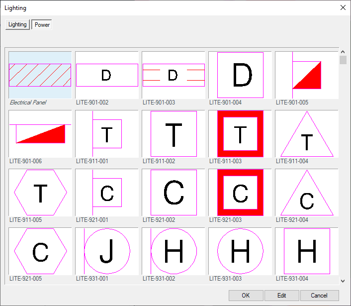
Select the Lighting tab to view the Lighting symbol library, or the Power tab to view the Power symbol library.

Select a symbol to represent your item, such as a light fixture. The following dialog box will open.
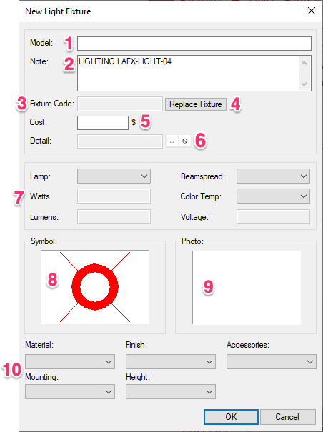
1. Enter a model name for the generic component you're adding.
2. Add a note about the component.
3. The Fixture Code field will be blank.
4. Replace Fixture: Click this button to select a different component.
5. Assign a per-unit Cost to the generic component you're adding.
6. Assign a detail to the component, or remove a detail association from the component.
7. Use these menus to configure options such as lamp type, beamspread, and voltage.
Take care to input the power and voltage minimum and maximum for generic or custom fixtures in the following formats:
- Power: minW|maxVA (where min is the fixture's minimum wattage and max is its maximum volt-amps – example: 2.5W|3.75VA).
- Voltage: minV|maxV (where min is the fixture's minimum voltage and max is its maximum voltage – example: 10V|15V).
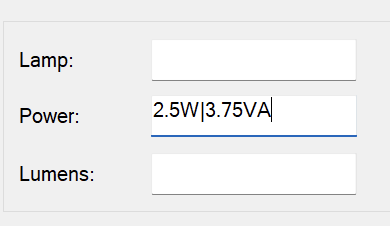
Power input minimum and maximum, example
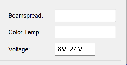
Voltage input minimum and maximum, example
Failure to use these formats will result in an errant voltage message and calculation, and will prevent our Verify tool from running properly on these fixtures.
8. Thumbnail image for the symbol currently assigned to the generic component. Click here to select a new symbol.
9. Thumbnail image for the photo currently assigned to the generic component. Click here to browse to and select a new photo. You'll be able to place the photo in your drawing using our Photo Callout tool.
10. Additional options to configure, including material, finish, and mounting select.
Adding Auxiliary Equipment
Auxiliary lighting equipment may include:
- Hubs/junction boxes
- Controllers
- Photocells/light sensors
To add auxiliary lighting equipment, select the Auxiliary option, then click New.
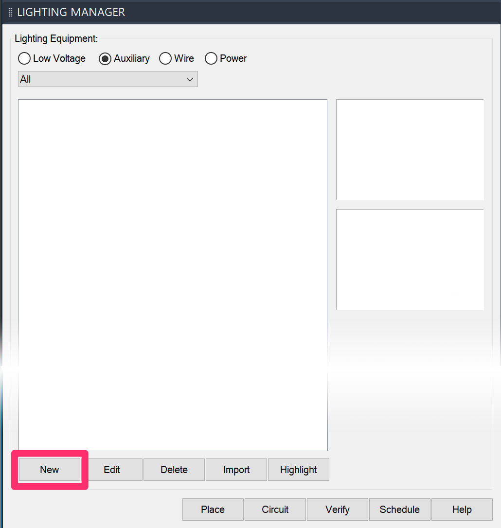
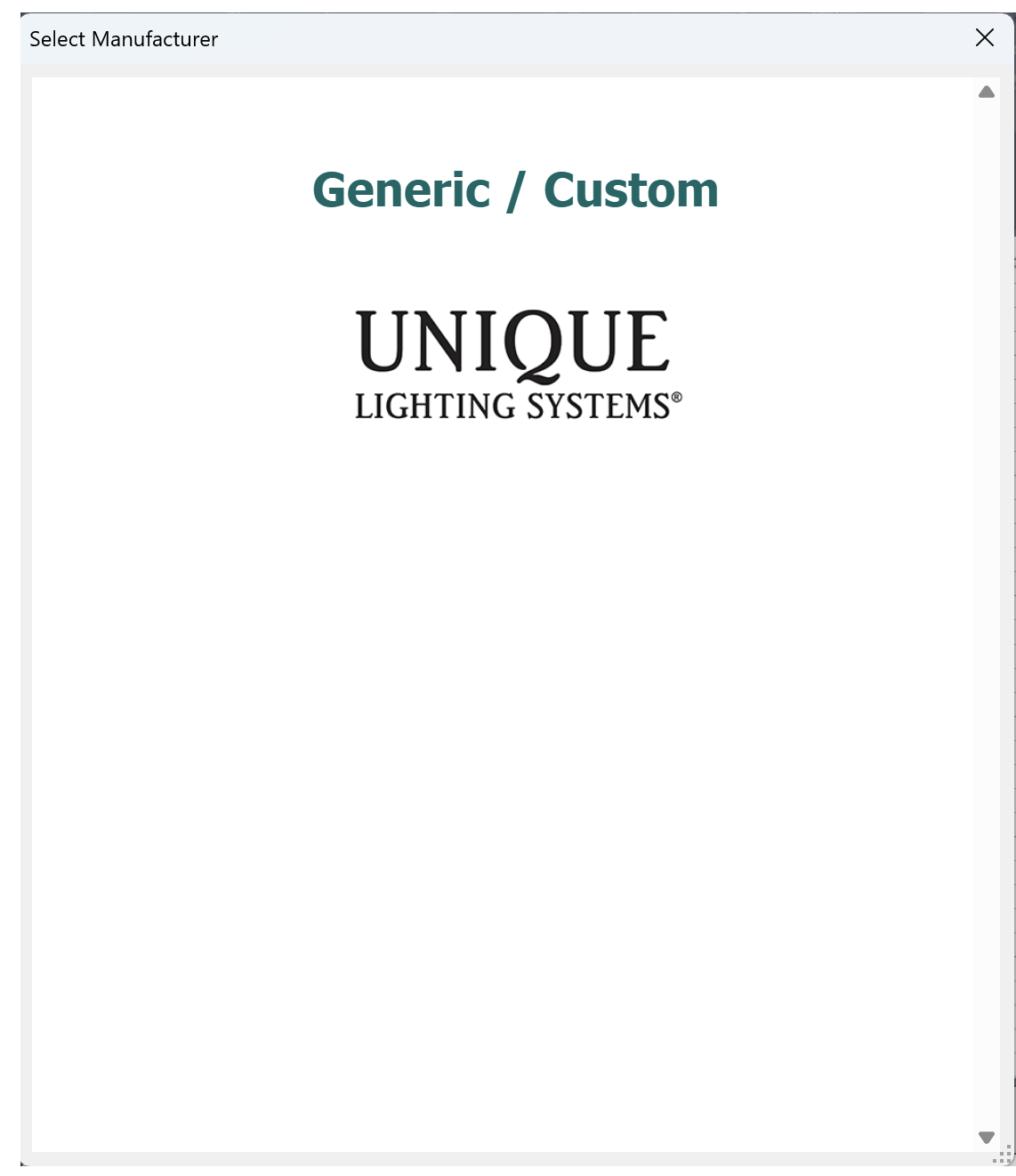
Select an auxiliary equipment manufacturer, or click Generic/Custom to add your own custom equipment, or equipment not offered by a Land F/X partner manufacturer.
If you selected a manufacturer, the New Light Fixture dialog box will open and you can select an equipment series.
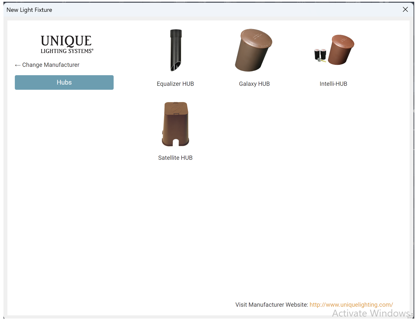
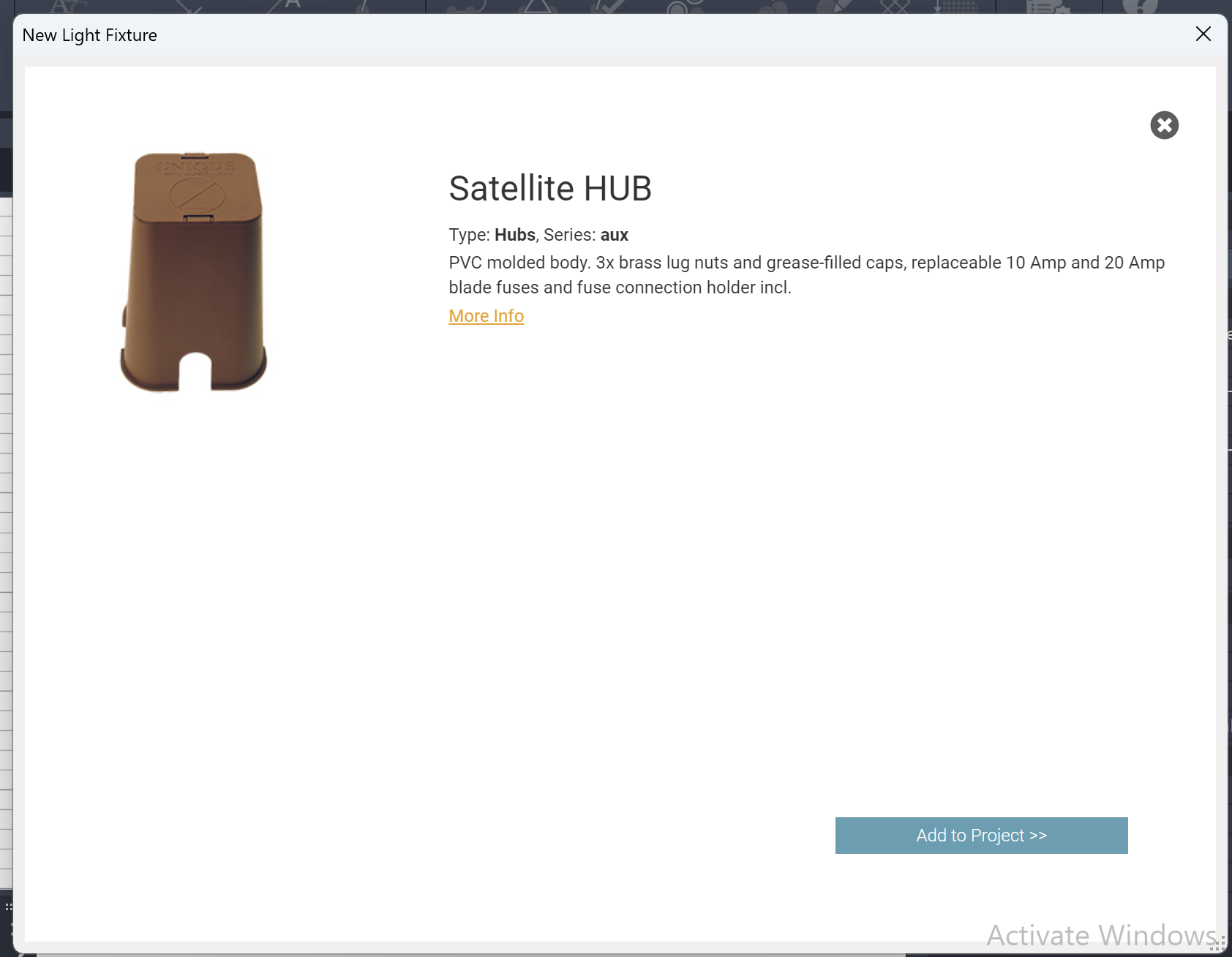
Select a model from the series you selected, then click Add to Project to add the equipment to your project.
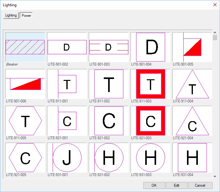
If you clicked Generic/Custom when adding new auxiliary eqipment, you'll see a dialog box where you can select a symbol for the equipment you're adding. Click OK after selecting the symbol.
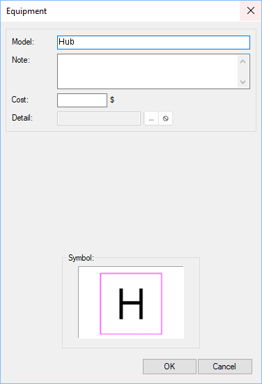
Enter all the info you want to include about the generic or custom equipment you're adding, including the model and any notes you want to associate with the equipment.
Click OK to add the generic or custom equipment to your project.
Adding Wire
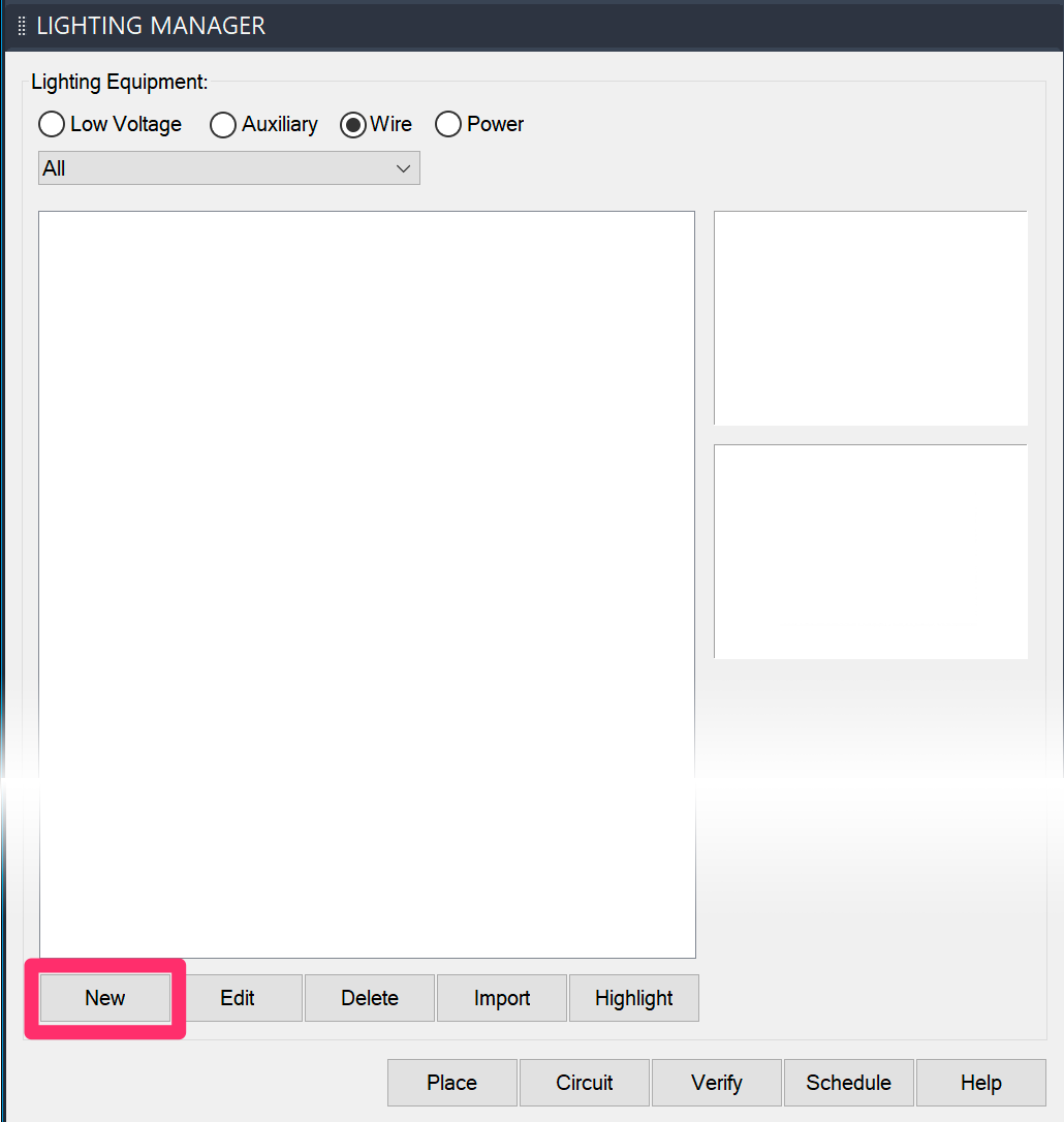
To add wire to your project, select the Wire option, then click New.
The Wire dialog box will open. You can now configure the wire type you want to add to your project.
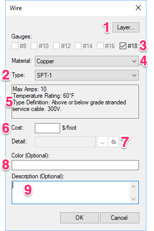
1. The wire will be assigned to our default layer for wire automatically. Click this button to move drawn wire to the layer of your choice.
2. Use this menu to select a wire type to use in your project.
3. After selecting your wire type, select a wire gauge (or, if required, two or more consecutive gauges) of wire.
4. Also after selecting your wire type, use this menu to select a wire material.
5. Information about the selected wire type appears in this text box.
6. Assign a Cost per unit of measurement (e.g., foot or meter) to the wire type you're using.
7. Assign a detail to the selected wire type, or remove a detail association from the wire type.
8. Enter a color of wire to use in the project.
9. Enter a description of the wire type.
Click OK to add the wire to your project.
Adding Power Equipment
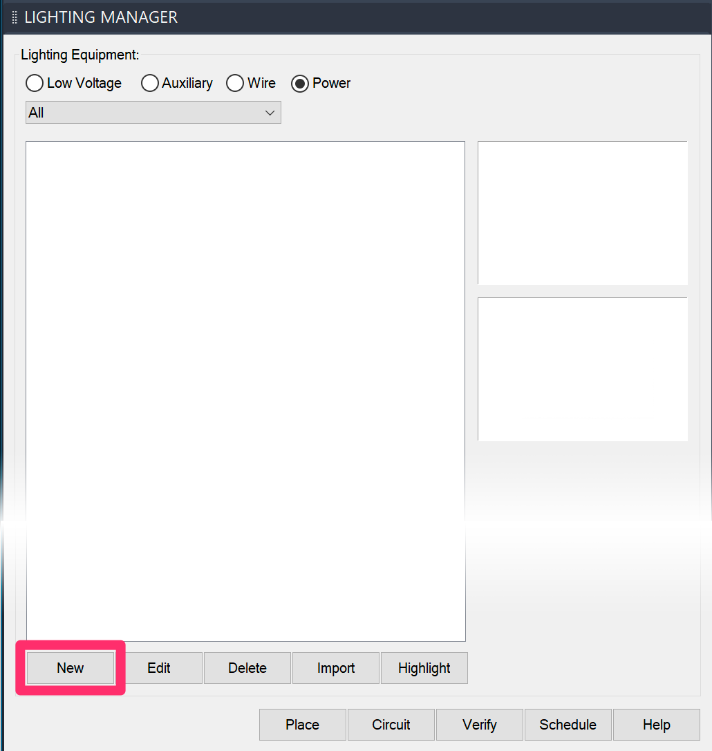
To add power equipment (i.e., an electric panel or transformer), select the Power option, then click New.
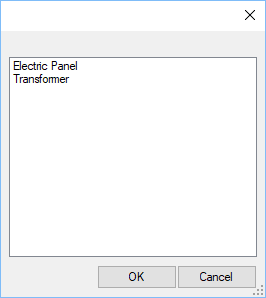
Select the option to add either an Electric Panel or Transformer, then click OK.
You won't have the option to add a transformer until you've added an electrical panel to your project.
Adding an Electric Panel
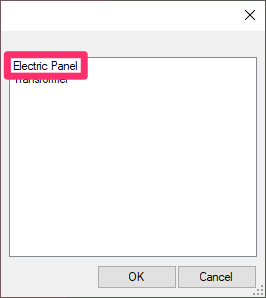
Select the Electric Panel option to add an electric panel to your project.
Select a symbol to represent your panel.
You can now configure the panel you want to use as the power source for your project.
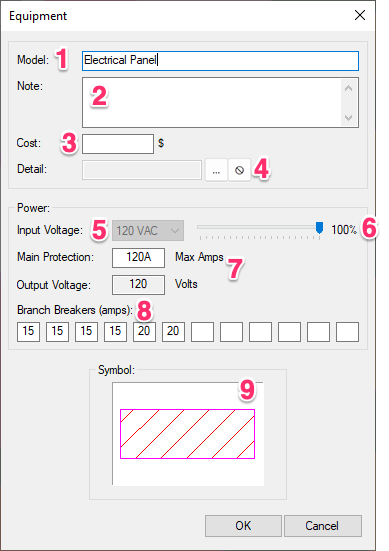
1. Enter a model name for the panel you're adding.
2. Add any notes you want to include about the panel.
3. Add a Cost for the panel you're adding.
4. Assign a detail to the panel, or remove a detail association from the panel.
5. The Input Voltage for the panel. This figure should be the source voltage supplied to your site.
6. Use this slide to account for any voltage fluctuation, or leave it at 100% if you don't anticipate any fluctuation.
7. The maximum amps this panel can supply, or the main breaker rating. Note that the output voltage you see here is not the panel's maximum voltage. It’s the input voltage multiplied by the fluctuation slider value.
8. Each of these fields represents one of the branch breakers you'll assign to the panel, with each field listing the amperage of the corresponding breaker. These fields default to the numbers you see here, but they're also completely customizable. You can:
- Add new breakers by typing their amperage into one of the blank fields
- Change the amperage in any of the existing fields to account for the corresponding breaker
- Delete any of the existing breakers by deleting the amp number in the corresponding field
9. Thumbnail image for the symbol currently assigned to the panel. Click here to select a new symbol.
Click OK when you're ready to add the panel. It will be listed under Power Equipment in the Lighting Manager.
Adding a Transformer
Select the Transformer option to add a transformer to your project.
To add a transformer to your project, you'll first need to add an electrical panel.
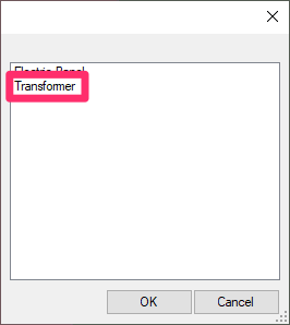
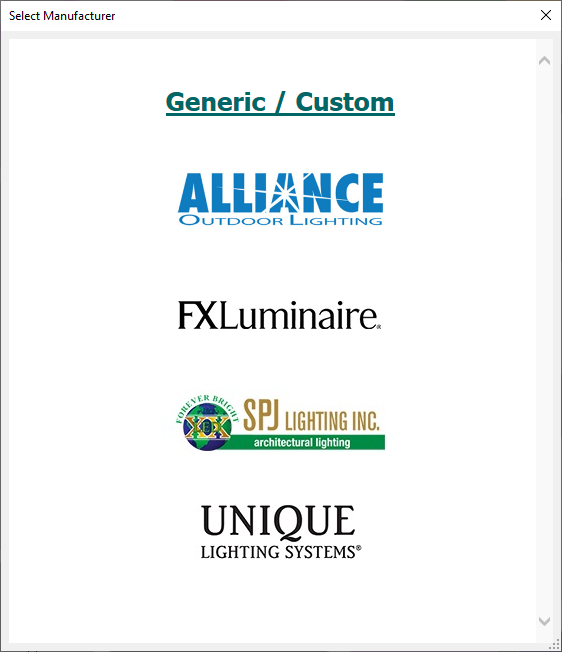
Select a transformer manufacturer, or select the Generic/Custom option to configure your own custom transformer.
If you selected a manufacturer, select a transformer model from that manufacturer.
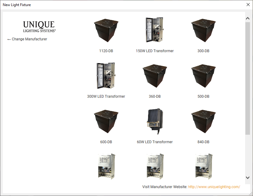
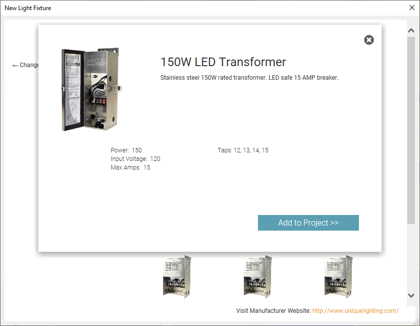
If you selected a transformer model from a manufacturer, you'll now see further information about the transformer you've selected, including its wattage rating, input voltage, maximum amperage, and the voltage of each of its output taps.
Click Add to project to continue adding the transformer to your project.
Select a symbol to represent the transformer you're adding.
You can now configure the transformer you want to use as the power source for your project.
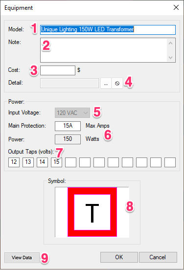
1. The model name for the transformer you're adding.
2. Add any notes you want to include about the transformer.
3. Add a Cost for the transformer you're adding.
4. Assign a detail to the transformer, or remove a detail association from the transformer.
5. The Input Voltage for the transformer.
6. The maximum amps and watts that will apply to the transformer. The maximum amperage value here refers to the low-voltage (output) side of the transformer.
7. Each of these fields represents one of the output taps assigned to the panel, with each field listing the voltage of the corresponding tap.
8. Open the manufacturer's website to view data associated with the selected transformer model.
These output tap fields are customizable for generic transformers, but not for manufacturer transformers.
As long as you've added a custom/generic transformer, you can:
- Add new taps by typing their voltage into one of the blank fields
- Change the voltage in any of the existing fields to account for the corresponding tap
- Delete any of the existing taps by deleting the voltage in the corresponding field
If you've added a manufacturer's transformer, you won't be able to add to, edit, or delete the tap voltages set by the manufacturer.
8. Thumbnail image for the symbol currently assigned to the transformer. Click here to select a new symbol.
Click OK when you're ready to add the transformer. It will be listed under Power Equipment in the Lighting Manager.
Placing Lighting Equipment
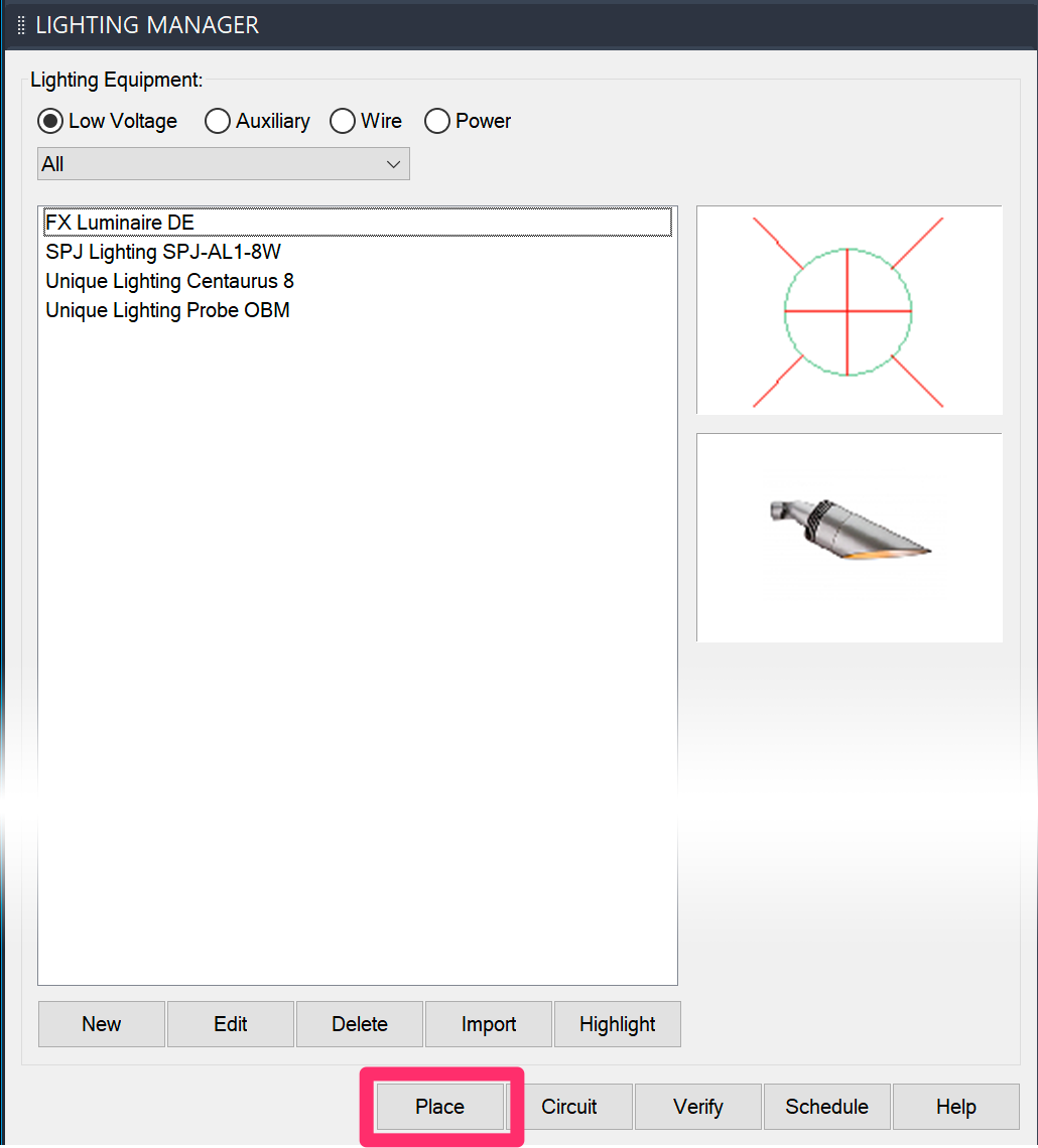
With your drawing open in Model Space, go to the Lighting Manager.
Select the item you want to place, then click Place.
Placing Fixtures, Auxiliary Equipment, and Power Equipment
To place lighting fixtures, auxiliary equipment, or power equipment, simply click to place the item in your drawing.
Depending on the equipment or model you've selected, you may need to click again to set its rotation in your drawing.
Light Throw Previews for Fixtures
If a light fixture has a manufacturer-provided IES file associated with it, a preview of its light throw will appear on the plan along with the symbol.
Only some of the light fixtures in our collection have manufacture-provided IES files, so not all fixtures will show up with a throw.
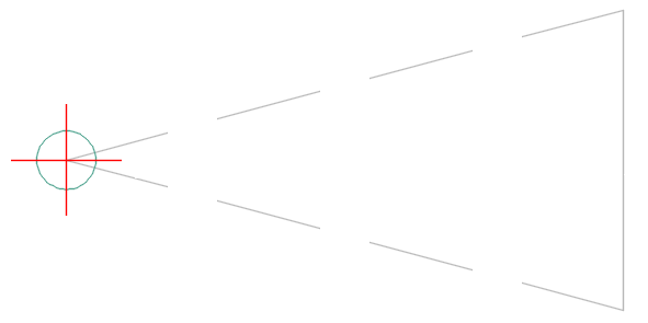
Here is an example of an uplight that includes an IES file – the Probe OBM by Unique Lighting.
The light throw appears in the drawing as a horizontal cone depicting a spotlight aimed parallel to the ground.
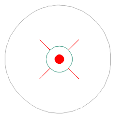
And here is an example of a path light that includes an IES file – the Centaurus 8, also by Unique Lighting.
This path light's throw appears in the drawing as a circle depicting a path light projecting light symmetrically, 360 degrees around itself, onto the ground.
Quick video
Placing Wire
When placing wire, you'll simply connect the dots between your power source and all your fixtures and other equipment – just like how you would pipe between irrigation equipment when using our irrigation tools.
When you click Place with a wire selected in the Lighting Manager, the cursor will turn into a pickbox, and you can begin wiring your fixtures.
In this example, we'll wire the simple array pictured to the right, including the power source and transformer.
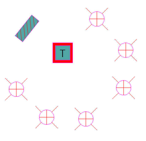
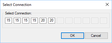
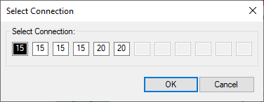
When wiring to a panel or transformer, you'll see a dialog box showing all the branch breakers (for panels) or output taps (for transformers). Select a connection and click OK.
If you've already wired to any of the connections on that panel or transformer, you'll see which connection(s) are already wired.
Click a fixture or other component to wire to it.
If you connected successfully, you'll see a yellow circle around the component.
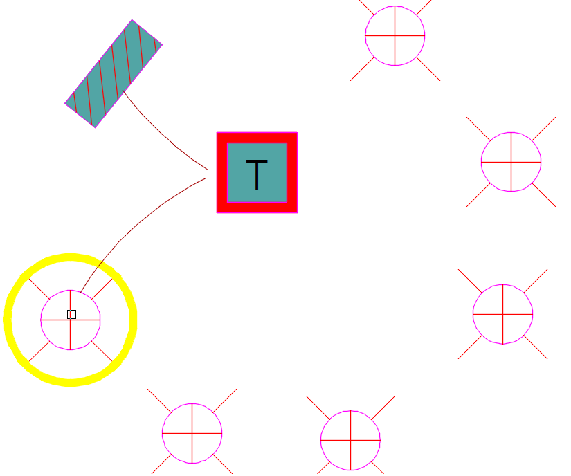
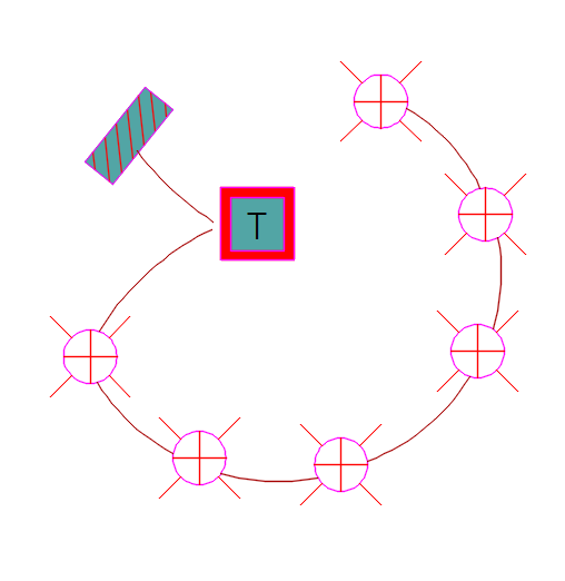
Keep placing wire in this way until you've completed the circuit.
Continue wiring any additional circuits from your panel or transformer.
Note that when you've already wired to a panel or transformer, the branch breaker or voltage tap that's already wired will show up as dark, as pictured t to the right. Select any of the other connections for wiring the new circuit.
If necessary, you can edit any panel or generic/custom transformer to add or make changes to these connections. Manufacturers' transformers will have their number of voltage taps, and the voltages for each of those taps, already set from the factory.
Connecting Different Wire Gauges or Types
Land F/X doesn't allow lighting wire to be connected to other wire types. Instead, you'll need to connect to a hub. If you need to connect different wire gauges or types of lighting wire, we recommend using auxiliary equipment. Use any symbol from our library you want, then configure the auxiliary equipment's name and description to represent your specific needs for that item.
Lighting Equipment and Work Areas
Special note about lighting equipment using IES files to display the light beam spread: This equipment is currently not capable of scaling as it is placed into a Work Area whose scale differs from the overall drawing plot scale. They only scale based on the drawing plot scale itself. For this reason, we highly recommend keeping lighting plans in separate drawings if they have different scales.
Editing Lighting Equipment
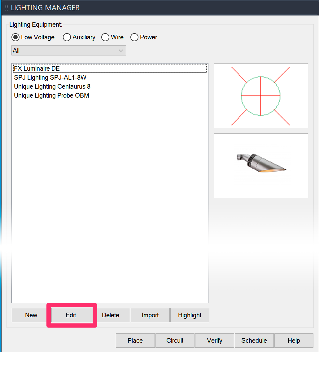
To edit a fixture or other piece of equipment in the Lighting Manager, select it and click Edit.
You can also use our Edit Object/Block Data tool to select a component you've already placed in your drawing. This tool opens a pickbox, which you can use to select the component in your drawing you want to edit.

You can now make changes to the component you selected. You'll see a slightly different dialog box when editing each type of lighting equipment (examples pictured below).
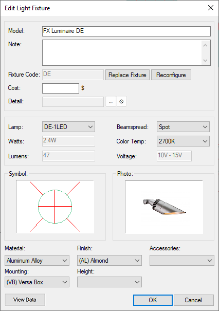
Dialog box for editing a light fixture – note the Reconfigure button, which allows you to select different configuration options.
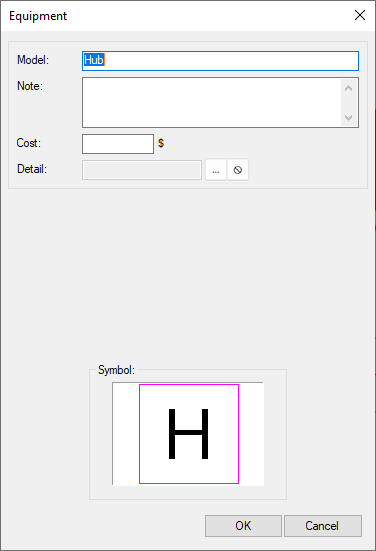
Dialog box for editing auxiliary lighting equipment
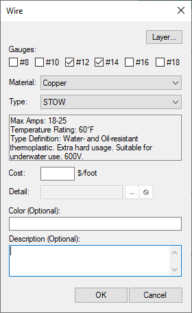
Dialog box for editing a wire type
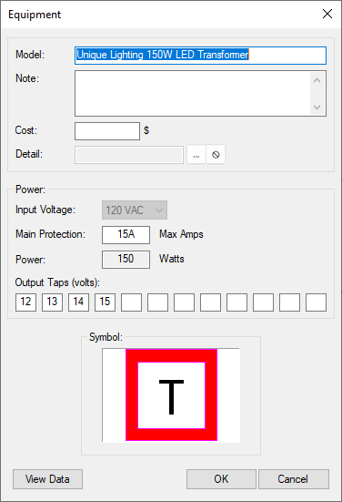
Dialog box for editing lighting power equipment (transformer shown)
When editing a transformer or electric panel you've already wired to other components, note that the dialog box will show which output taps (for transformers) or branch breakers (for panels) are already connected.
Click OK when finished making your edits.
Creating Circuits, or Zones
With our Circuit tool, you can divide your lighting plan into circuits, or zones, before you've even wired your fixtures. Each circuit will have its wattage total calculated automatically, giving you a good idea of the power your system will need to provide in each region, and in total.
For more information and instructions, see our documentation on creating lighting circuits (zones).
Generating a Lighting Schedule
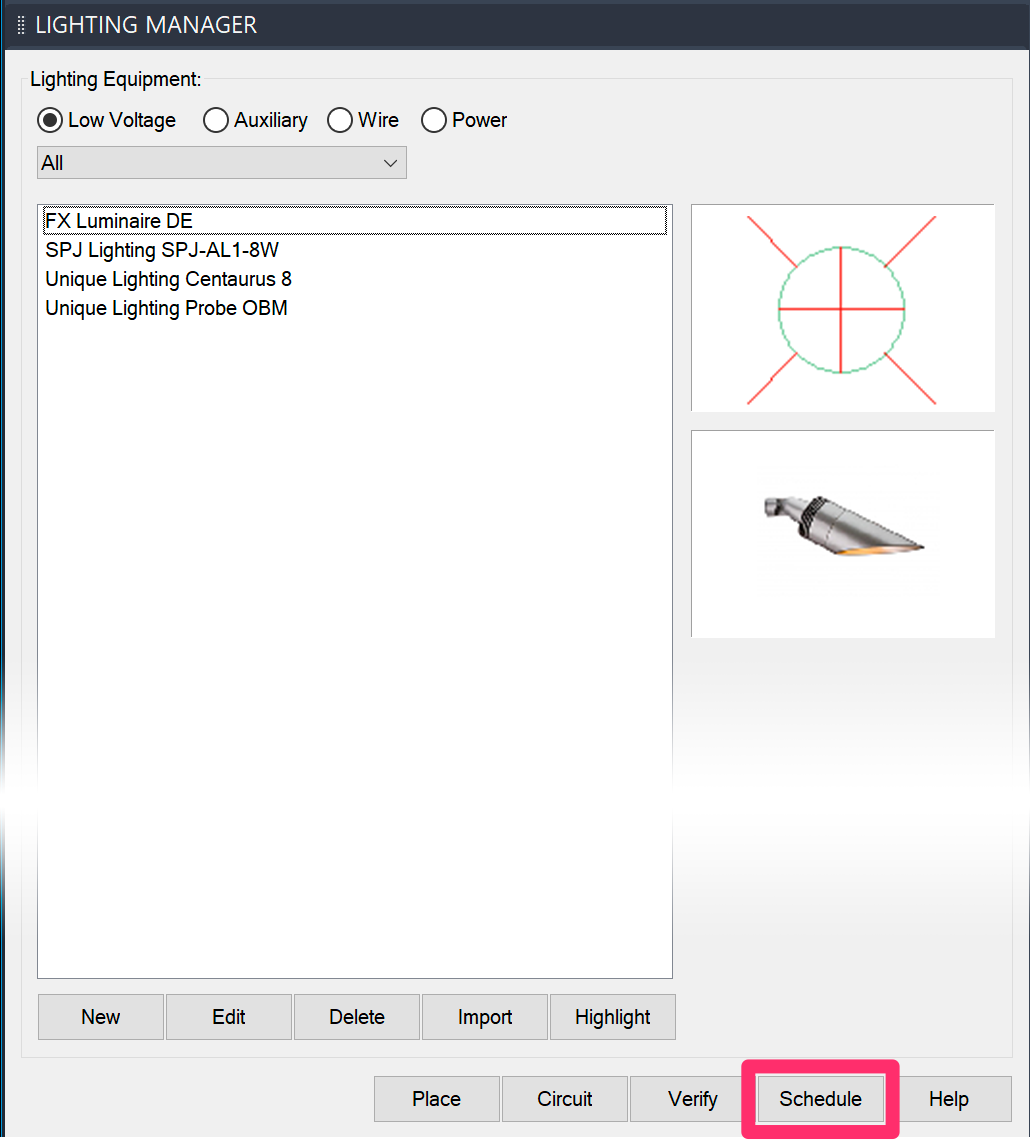
You can place a schedule of lighting equipment you've used in your project within either Model Space or a Paper Space Layout Tab by opening the Lighting Manager and clicking Schedule.
For more information and instructions, see our article on placing a Lighting Schedule.
Labeling Fixtures, Wires, and Equipment
Although we offer the ability to call out lighting features individually, many designers prefer using the Lighting Schedule to show the various lights used in a plan.
You can use our Reference Note Callout tool to label your lighting fixtures, wires, and equipment. For more information and instructions, see our article on labeling your lighting plan.
Labeling Lighting Equipment Using Photo Callouts
You can also use our Photo Callout tool to label lights with their respective photos. For more information, see our Photo Callout page.
Photometric Data Via IES File Compatibility
Quick video
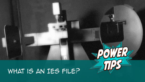
Our lighting module is now compatible with IES files. These files, available from fixture manufacturers, contain a digital profile of a light’s photometrics – a mapping of light distribution.
With manufacturer IES data, we're able to give a footprint preview of the light at 50% luminosity, ensuring that you get the best light coverage from CAD.

With manufacturer IES data and 3D support, you can take your lighting fixtures into SketchUp and, through a light-rendering add-on, see how the light can interact with the surrounding site after installation.
Lamp Color & Color Temperature
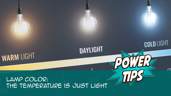
When selecting fixtures and lamps, you may encounter a specification called color temperature. Wondering what color temperature is all about? Check out the Power Tip video linked to the right, where we go over the meaning of color temperature in the context of landscape lighting design, explain the color temperature scale, show how to factor color temperature into your design effectively, and discuss the role (or lack thereof) played by color temperature in wildlife-safe lighting.
Importing Lighting Equipment from a Template or Project
If you find yourself adding the same equipment to multiple projects, we recommend setting up a project template and then adding your commonly used equipment to that template. You can then import those items into a new project from that template. This practice can save you immeasurable amounts of time, considering all the data you need to fill out for each component you add to a project. With templates, you only need to add and configure your equipment once, then simply import them and attached data into the present project.
The following steps also apply to importing equipment from regular Land F/X projects. However, we recommend setting up and importing from a template – mainly because templates are set up to be read-only. This means you can rest assured that the data in your templates hasn't changed when you import your equipment into a project.
To import equipment into the current project, open the Lighting Manager and click Import.

The Select Project dialog box will open.
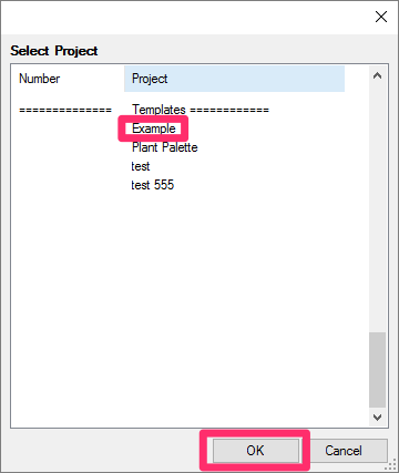
Select the template or project that includes the equipment you want to import.
Click OK.
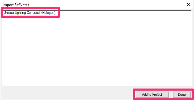
The Import RefNotes dialog box will open.
Highlight the items you want to import, and click Add to Project to add them to the current project.
Click Done when finished.
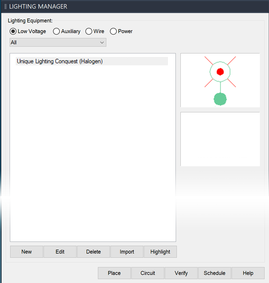
The equipment you imported will now be listed in the Lighting Manager.
Those components, and all associated data, is now added to your project, and you can place it as needed.
Error Checking Your Lighting Plan (Verify Wiring)
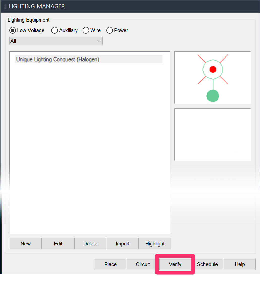
Our Verify tool provides a quick and easy method for checking your lighting plan for errors and correcting them.
For more information and instructions, see our article on checking your lighting plan for errors.
Edit our Lighting Symbols, or Add Your Own
Want to customize the lighting symbols? You can edit our default symbols or add your own custom symbols to our library. More information
Related Webinars
- Working with Lighting Tools in Land F/X: We overhauled our lighting module in 2019, adding multiple new capabilities and improving the existing functionality. Take a tour of our greatly improved lighting tools, and learn how to use them to your advantage. (1 hr 8 min)
- Twilight Highlights: Learn how Land F/X and the Twilight Render plugin for SketchUp will streamline the rendering process for your lighting plan. We'll show you how to create realistic renders, using accurate models of landscape lighting manufacturers' light fixtures, in no time. (1 hr 1 min)
- Landscape Lighting Codes, Guidelines, and Techniques: Brian Qualls of Unique Lighting shares some resources to inform new designers and seasoned professionals alike before they dig into our revamped lighting tools. Learn primary lighting codes and ordinances, design guidelines and strategies, and landscape-specific techniques for effective and efficient lighting design. (1 hr 2 min)
- Designing for Lighting Effects: Ryan Williams of FX Luminaire provides some valuable pointers on ensuring that each of your lighting jobs is creative and unique and doesn't fall into the routine of designing on autopilot. (57 min)
- A Practical Approach to Low-Voltage Lighting Design: Brian Qualls of Unique Lighting Systems goes over the fundamentals of lighting design, including fixture placement, visual objectives, proper transitions, and the three levels of light. (53 min)
- Looking Back on Development in 2019: We look back on some of the feature highlights from 2019 and give you a sneak peek into how some of those features have come to fruition – including our award-winning lighting module. (39 min)
- Understanding the Manufacturer Connection: The Manufacturer Connection is a dynamic and invaluable relationship that we at Land F/X have pioneered into an exclusive, easy to use tool that benefits both designers and manufacturers. Learn about the work we put into manufacturer content and how to enhance your CAD design and specification processes for site amenities, lighting, and hardscape. (1 hr 1 min)
- A Practical Approach to Engineering the System (Low-Voltage Lighting): Aimed at landscape architects and other designers, this webinar will show the engineering side of a low-voltage system. We'll move past the idea that "we are not electrical engineers" and show you how low-voltage lighting has the same design fundamentals as irrigation systems. (52 min)
- How The Manufacturer Connection Works: The Manufacturer Connection is the relationship between the designer and manufacturer that Land F/X has used to separate ourselves from other design software programs. Learn how it works. (53 min)
Troubleshooting
Issue: You are unable to send your Lighting Schedule to an Excel spreadsheet
Issue: Bad DXF group (10) error when placing lighting equipment
Issue: Text in the Lighting Schedule columns is overlapping
Issue: Error: "Unhandled exception in dcl-slideview-load ARX" when placing lighting equipment
Issue: CAD freezes or lags after you place a Lighting Schedule


