Concept Graphics Manager
Quick video
- Schedule Text in Uppercase (or Upper and Lowercase)
- Work Areas and Concept Graphics Schedules
- Creating a Background Fill or Mask for Your Schedule
- Concept Graphics Schedule and Slope Areas
Concept Graphics are blocks placed in your drawing that relate to an extremely diagrammatic, conceptual level of site planning. These graphics are used for creating schematic designs, and are representative of objects or ideas. They include Viewpoints, Custom Nodes, and Custom Lines.
Concept Graphics should only be placed in Model Space. When placed in Paper Space, they won't scale correctly.
Overview of Concept Graphics
Open the Concept Graphics tool:

F/X Site ribbon, Concept flyout
or type FX_ConceptGraphics in the Command line
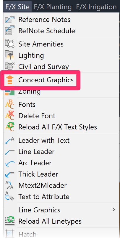
F/X Site pull-down menu
The Concept Graphics Manager will open.
The Concept Graphics Manager is now a docked palette, allowing you to continue working in your drawing while managing your project's Concept Graphics.
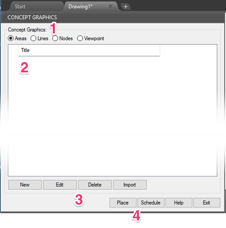
1. Select the Concept Graphic category you want to add: Area, Lines, Nodes, or Viewpoint.
2. Concept Graphics you create will be listed in this area.
3. Buttons to add a New Concept Graphic to the selected category, Edit or Delete a selected Concept Graphic, and Import Concept Graphics from another project.
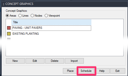
4. Buttons to Place a selected Concept Graphic into a drawing and generate a Concept Graphics Schedule
Areas
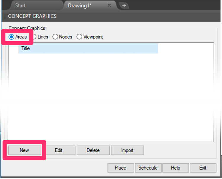
The Areas option allows you to add areas from our Site Development tool to your Concept Graphics.
To add an Area, select the Areas option in the Concept Graphics Manager.
Then click New.
For more information on how Areas work, see our Concept Graphics Areas (Site Development) page.
Concept Lines
A Concept Line is typically used to represent a linear usage such as pedestrian or vehicular travel. It can also represent an area to be screened or define the boundary of a usage area.
To add a Concept Line, select the Lines option in the Concept Graphics Manager.
Then click New.
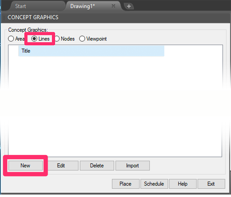

You'll now see a dialog box with a number of graphic options for the Concept Line you're adding.
Select a line style, and click OK.
Did you know that Concept Lines are completely customizable? You can find the source files in the folder LandFX\Blocks\Graphics\Concept\Lines. For instructions on editing these Concept Line source files, please see our Customize Concept Graphics page.
Do you see blank rectangles rather than slides in this dialog box? Or are the slides of poor quality, as pictured below?

If so, here's the fix.
The New Concept Item dialog box will open. Here, you can fill in information about the line usage.

1. The Title of the line usage
2. If you want, add a Note to describe what the Concept Line represents.
3. Enter a Width for the Concept Line.
4. A preview of the symbol you assigned to this Concept Line
5. The color given to the line. When you first create the line, the color is a default gray. Click the Color box to assign a new color to the line.
6. Choose whether or not you want your Concept Line to include a Gradient.
7. Click this button to associate a Photo with the Concept Line. You can then choose to call out your Concept Line using this photo.
A typical usage of a Concept Line might be a bike path.


Click the Color box to select a fill color for the Concept Line.
Select a color from either the True Color tab or the Color Books tab.

True Color tab selected

Color Books tab selected
True Color offers millions of color options. However, these colors may vary in appearance from one computer monitor to another. This seems to be the most common type of color selection.
Color Books are generally a graphic art standard of Pantone color books. You would most likely use one of the printed Pantone color books in selecting this color to ensure its output would be exactly as you anticipate.
DO NOT select a color from the AutoCAD Index Color tab.
The AutoCAD Index Color palette is generally reserved for color-dependent plot styles, and it offers only 255 color options.

Once you select a color, it will show up in the Color area.
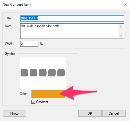
You'll notice that Concept Lines have a gradient rather than a solid color. We don't have anything built into the system to turn off the gradient, as we do with the Site and Zoning areas. However, you can change a gradient fill to a standard solid fill using the AutoCAD Block Editor.
Concept Nodes
A Concept Node is a focal point or important usage. Examples might include a fountain plaza, a kiosk, a focal seating area, or simply a focal change of direction in a path system.
To add a Concept Node, select the Nodes option in the Concept Graphics Manager.
Then click New.
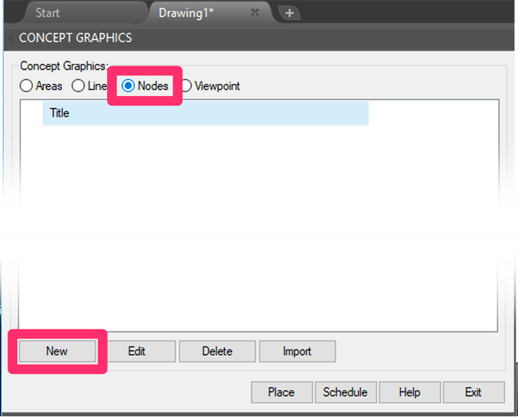

You'll now see a dialog box with a number of graphic options for the Node you're adding.
Select a Node style, and click OK.
Did you know that Concept Nodes are completely customizable? You can find the source files in the folder LandFX\Blocks\Graphics\Concept\Nodes. For instructions on editing these Node source files, please see our Customize Concept Graphics page.
Do you see blank rectangles rather than slides in this dialog box? Or are the slides of poor quality? If so, here's the fix.
The New Concept Item dialog box will open, allowing you to fill in information about your Node.

1. The Title of the node
2. If you want, add a Note to describe what the node represents.
3. Enter a Width for the Concept Node.
4. A preview of the symbol you assigned to this node
5. The color given to the node. When you first create the node, the color is a default gray. Click the Color box to assign a new color to the node.
6. Choose whether or not you want your Concept Node will include a Gradient.
7. Click this button to associate a Photo with the Node. You can then choose to call out your Node using this photo.
A typical Node might represent a seating focal point.


You can now assign a color to the node by clicking the Color box.
Select a color from either the True Color tab or the Color Books tab.

True Color tab selected

Color Books tab selected
True Color offers millions of color options. However, these colors may vary in appearance from one computer monitor to another. This seems to be the most common type of color selection.
Color Books are generally a graphic art standard of Pantone color books. You would most likely use one of the printed Pantone color books in selecting this color to ensure its output would be exactly as you anticipate.
DO NOT select a color from the AutoCAD Index Color tab.
The AutoCAD Index Color palette is generally reserved for color-dependent plot styles, and it offers only 255 color options.

Once you select a color, it will show up in the Color area.

Viewpoint
A Viewpoint graphic will typically reference a specific view of the project site. However, a Viewpoint can also serve a variety of other purposes, where you reference a notation relating to a direction.
To add a Viewpoint, select the Viewpoint option in the Concept Graphics Manager.
Then click New.
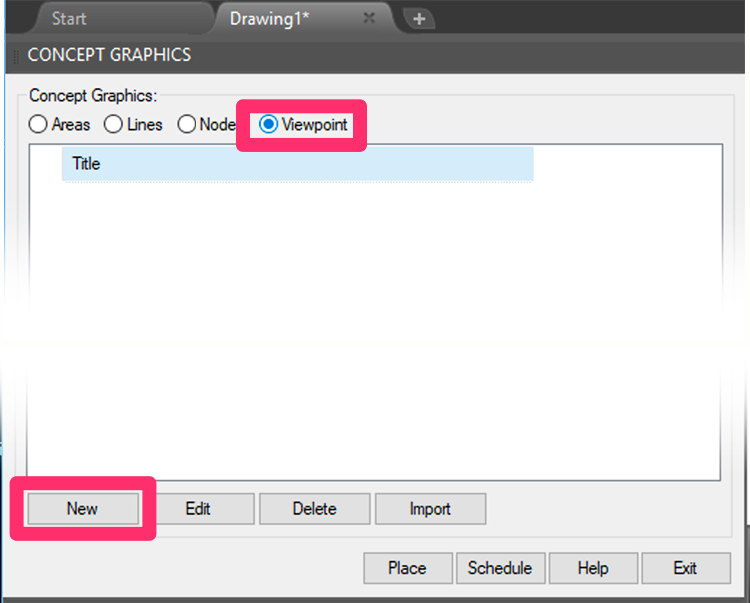
The New Concept Item dialog box will open, allowing you to fill in information about your Viewpoint.

1. The Title of what your Viewpoint represents
2. If you want, add a Note to describe the Viewpoint.
3. The Number that will appear in the Viewpoint. This number is editable, but can consist of no more than two characters.
4. Click this button to associate a Photo with the Viewpoint. You can then choose to call out your Viewpoint using this photo.
A typical Viewpoint might relate to a viewing of the site.
For example, it can point to an on-site or off-site usage to screen, such as an adjacent eyesore (see the example to the right).


You'll want a photo associated with your Viewpoint. Click Photo to assign one.
When you click Photo, you'll navigate to where the photo is stored on your computer.
The photo will need to be on a mapped letter drive, such as your server, a shared online folder, or even the C: drive on your computer.
When you select the photo, you'll see a thumbnail preview for it within the Symbol location.

- Viewpoint doesn't always mean the viewing of something, but might also relate to where a usage might want to be, or a usage to avoid. A photo of a particular view of the site is simply a logical use for a Viewpoint.
- If you assign photos to a Viewpoint, make sure the photo is in a stable file location. If you move the photo to a different directory on your computer, the link will be lost.
- You don't necessarily need to fill in the Title and Notes of a viewing. The Viewpoint might simply consist of a number of view callouts relating to a photo montage on this or another sheet.
Placing Concept Graphics
Placing a Concept Line
Select the Lines option in the Concept Graphics dialog box.
Highlight the Concept Line item you want to place. Then click Place to place the Concept Line.
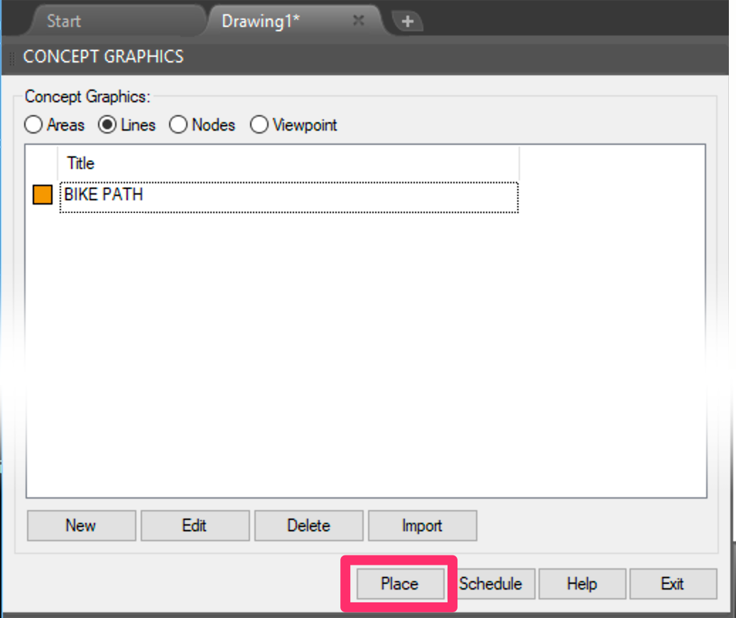
The cursor will turn into a pickbox and the Command line will prompt you to Select polyline, or [Draw]:
You can choose to:
- Select an existing polyline in your drawing or an Xref to turn into a Concept Line, or
- Type D to draw your Concept Line on the fly.
Selecting an Existing Polyline – Even in an Xref!
To select a polyline, just click it with the pickbox.
Yes, you can even select a polyline in one of your Xrefs!
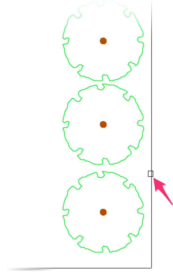

You'll be asked whether you want to place arrows at the end of the line.
Click Yes to include arrows, or No to exclude them.
If you clicked No, you'll now see your Concept Line.
If you clicked Yes, you'll see the Concept Arrows dialog box, where you can select an arrow for the ends of your line.
Click an arrow style to select it, then click OK to place the arrows.
You can also click Cancel to place the line without arrows.
If you only want an arrow on one end, select an arrow style and then use the Block Editor to edit the resulting Concept Line block to delete one arrow manually. Don't forget to save your changes. Block Editor instructions

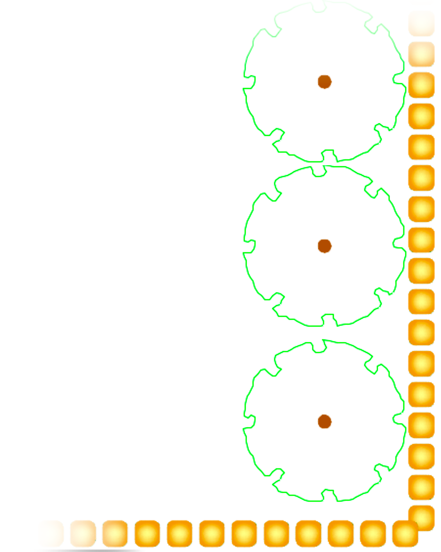
Your Concept Line will replace the polyline you selected.
To change the line back into a polyline, type FXplode in the Command line and press Enter. Then select the Concept Line. It will change back into the original polyline.
Drawing a Concept Line on the Fly
To draw your Concept Line on the fly, type D with the tool active.
Click to begin your line.

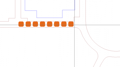
Move your mouse to begin drawing the line.
When you click to draw the first line segment, you can change direction of the line or draw an arc. The Command line will prompt: Next point, [Arc], <done>.
For an arc, type A to start an arc at the point where you clicked. The Command line will prompt you to set the Arc midpoint.
Click to set the midpoint of the arc, then click again to place the arc.


If you want another arc, repeat the arc process.
After drawing a line segment, you'll always revert automatically to drawing a "line" unless you type A to draw an arc.
In our example, we've drawn a short line segment extending upward to end our Concept Line.

Press Enter to end the command.

You'll be asked whether you want to place arrows at the end of the line.
Click Yes to include arrows, or No to exclude them.
If you clicked No, you'll now see your Concept Line.
If you clicked Yes, you'll see the Concept Arrows dialog box, where you can select an arrow for the ends of your line.
Click an arrow style to select it, then click OK to place the arrows.
You can also click Cancel to place the line without arrows.
If you only want an arrow on one end, select an arrow style and then use the Block Editor to edit the resulting Concept Line block to delete one arrow manually. Don't forget to save your changes. Block Editor instructions >


If you select an arrow style, arrows of that style will be placed at each end of the line.
The resulting line is one large block. If you make a mistake, delete the line and redraw it.
When the item is printed, the color will be indicated as Color, and the AutoCAD Index Colors used on the site will be black.

Placing a Concept Viewpoint or Node

In the Concept Graphics dialog box, select the Viewpoint or Nodes option.
Highlight the graphic you want to place. Then click Place.
In Model Space, click where you want to place the Viewpoint or Node.
If placing a Viewpoint, move the cursor until the Viewpoint is pointing in your desired direction. Click to set the direction.
The Viewpoint will be placed with the number assigned to it, as pictured to the right.


If placing a Node, just click to place it.
The image to the left shows an example Concept Node placed in a drawing.
Editing Concept Graphics
To edit a Concept Graphic from the Concept Manager, select it and click Edit.
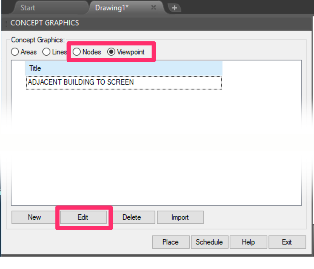
You can also use our Block Data/Edit Object tool to select a Concept Graphic you've already placed in your drawing. This tool opens a pickbox, which you can use to select the object in your drawing you want to edit.

The Edit Concept Item dialog box will open.
Here, you can make edits to the selected graphic's title, note, or number, or select a new symbol or photo for it.

Creating a Concept Graphics Schedule
To place a schedule of your Concept Graphics, click the Schedule button in the Concept Manager.
The Concept Graphics Schedule is now powered by our Reference Notes (RefNotes) Schedule feature, which we improved with some major updates as of August 2024. More information
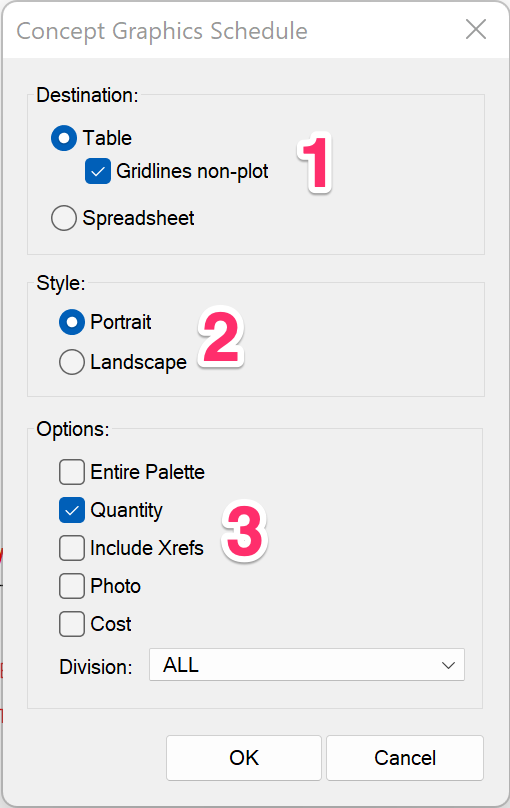
1. Select a destination for the schedule:
- Table: Place the schedule in your drawing as a table.
- Gridlines non-plot: Check this option if you want the lines separating the table cells to be non-plot. Uncheck this option if you want the table lines to plot.
- Spreadsheet: Export the schedule to a spreadsheet program such as MS Excel.
We've replaced the Drawing and Table options with this single Table option and the Gridlines non-plot checkbox. If you select Gridlines non-plot, the schedule will place with gray gridlines that will not show up when you plot your drawing (essentially the same as the former Drawing option). Deselecting this option will result in a schedule placing as a table with gridlines set to plot (essentially the same as the original Table option). This updated system allows you to edit your schedules much more easily.
2. Select the option to have your schedule appear in Landscape or Portrait layout.
3. Select any of the following options you want to include in your schedule:
- Entire Palette: List all Concept items from your project in your schedule, whether you've placed them or not.
- Quantity: Include the number of each Concept item you've used in your design.
- Include Xrefs: List Concept items in Xrefs within the schedule.
- Photo: Include a photo of each Concept item, if applicable, in the schedule.
- Cost: Add a cost for each Concept item.
- Division: Assign a Reference Note division to each Concept item and list the divisions in the schedule.
Click OK to place the schedule.

The Concept Graphics Schedule will include the photos you've assigned to each of your Concept Graphics.
Concept Lines and the Concept Graphics Schedule
We've redesigned the way Concept Lines appear in the Concept Graphics Schedule. The Lines now arrange vertically, with the intention of working better with an assigned photo and long description, as well as matching better when combined with Areas and Nodes.
Schedule Text in Uppercase (or Upper and Lowercase)
You can control whether the text in any of your schedules appears in all uppercase, or in upper and lowercase, from the General Preferences. For instructions, see our Schedule Text in Uppercase article.
This setting will apply to all schedules you place in your drawings, including:
- Plant Schedule
- Irrigation Schedule
- Details Schedule
-
Site schedules such as:
- Reference Notes (RefNotes) Schedule
- Lighting Schedule
- Concept/Site Development Schedule
- Zoning Schedule
- Grading Schedule
Work Areas and Concept/Site Development Schedules
Functioning essentially as drawings within a drawing, Work Areas allow you to divide your site into a number of distinct areas. In this way, you can break up your design into separate regions, phases, scope-of-work requirements, and virtually any other way you can imagine. This feature makes it possible to limit any of your site schedules, including the Site Development Schedule, to specific Work Areas. You can also break up your schedule to show separate summaries of Site Development items in each Work Area. For information on dividing your Concept Graphics Schedule (or any other site schedule) in this way, visit our Limiting Site Schedules With Work Areas page.
Keep in mind that our software does not allow you to split a single hatch (such as a Conceot Area hatch or color) between multiple Work Areas. Splitting hatches in this way is not possible for a number of reasons – primarily because the only way to do so is to convert every hatch to a Region object, and then perform a Union and Subtraction against the Work Area in order to determine the area inside vs. outside the hatch.
This process can misfire because not all hatches can be converted to Region objects. Allowing splitting of hatches would require the software to highlight those areas in some fashion to alert users to them. But more importantly, that process of converting to Regions and Union/Subtracting takes time. For a complicated design with hundreds of areas could easily chug the computer for a number of minutes. While of course some users would be willing to accept that hit, we feel it's a bit beyond the acceptable range of about 7 seconds for the computer to finish doing whatever it was doing.
Even more importantly, splitting jobs into zones or phases typically coincides with a desire to turn off or half-tone the objects outside of the current viewport. In order to do this, you would need to draw the hatch as two separate hatches.
But after all that explanation, we do believe that the ability to split hatches between Work Areas would be a handy feature to include in the software! In the future, as the Region functions become more reliable and a bit quicker, we will certainly be adding this functionality.
Create a Background Fill or Mask for your Schedules
Some designers want to give their schedules a background fill to allow it to pop from the rest of the drawing. You can create a background fill for your schedule using the Table Style Manager. Find out how.
Concept Graphics Schedules and Slope Areas
Slope Areas work with our Slope Callout tool to apply a specific grade percentage or ratio to a closed polyline area in your drawing. Objects represented by any smart hatches within those closed polylines (Slope Areas) will have their quantity, volume, or area recalculated based on that slope percentage or ratio.
If you run a Concept Graphics Schedule in a drawing that includes one or more Slope Areas, the schedule will scan all Concept Area hatches to determine whether they are inside a Slope Area. If so, the schedule will recalculate the square footage/meters of those areas.
Slope Areas in Xrefs
Schedules will recognize Slope Callouts in Xrefs, as long as the Xref is on the layer L-SLOPE-AREA and the schedule is configured to include Xrefs. Schedules configured to include Xrefs will also recognize Slope Areas in the live drawing even if the Concept Areas calculated by the schedule are in an Xref.
Placing a Photo Callout
Like other photo callouts, photos associated with Concept Graphics need to be placed in Paper Space.
To place a photo associated with a Concept Graphic, go to the layout (Paper Space) tab where you plan to place the photo.
You'll need a viewport of the site where you can see the Concept Graphics you've placed. Follow our instructions to lock the viewport.
If the layout tab doesn't require a viewport of the site, make a temporary one off to the side. Double-click within the viewport to work within that viewport area, or what is called “floating Model Space.”
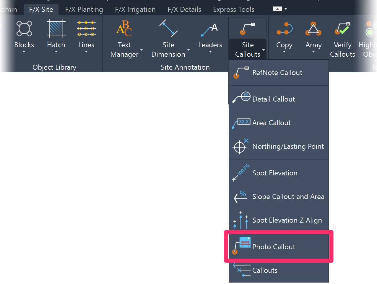
Place your photo using our Photo Callout tool. Open Photo Callout:
&nsbp;
F/X Site ribbon, Photo Callout flyout

F/X Planting ribbon, Photo Callout flyout
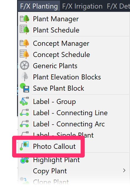
F/X Planting pull-down menu
or typeFX_PlantPhotoCallout in the Command line
Still in your layout tab, click the Concept Graphic item you'd like to call out with a photo.
You'll see a preview of the photo, as pictured to the right.
Click OK to accept the photo, or click Browse to browse to a new photo.


Review the caption to be placed beneath the Photo Callout.
You can also choose whether to include a drop shadow with your Photo Callout.
Click OK to place the photo.
You'll be brought back to Paper Space from the floating Model Space. Click to place the photo, then drag the mouse to size it. If you're calling out a Node or a Line, you'll be prompted to place a callout leader.
If you're calling out a Viewpoint, you'll see a circle containing the Viewpoint number next to the photo caption.
Viewpoint Photo Callouts do not have leaders.

Importing Concept Graphics from a Template or Project
If you find yourself adding the same Concept Graphics to multiple projects, we recommend setting up a project template and then adding your commonly used Concept Graphics to that template. You can then import them into a new project from that template. This practice can save you immeasurable amounts of time, considering all the data you need to fill out for each Concept Graphic you create.
With templates, you only need to add and configure your Concept Graphics once, then import them, along with all attached data, into the present project.
The following steps also apply to importing Concept Graphics from regular Land F/X projects. However, we recommend setting up and importing from a template – mainly because templates are set up to be read-only. This means you can rest assured that the data in your templates hasn't changed when you import your Concept Graphics into a project.
To import Concept Graphics into the current project, select a category in the Concept Graphics Manager.
Then click Import.
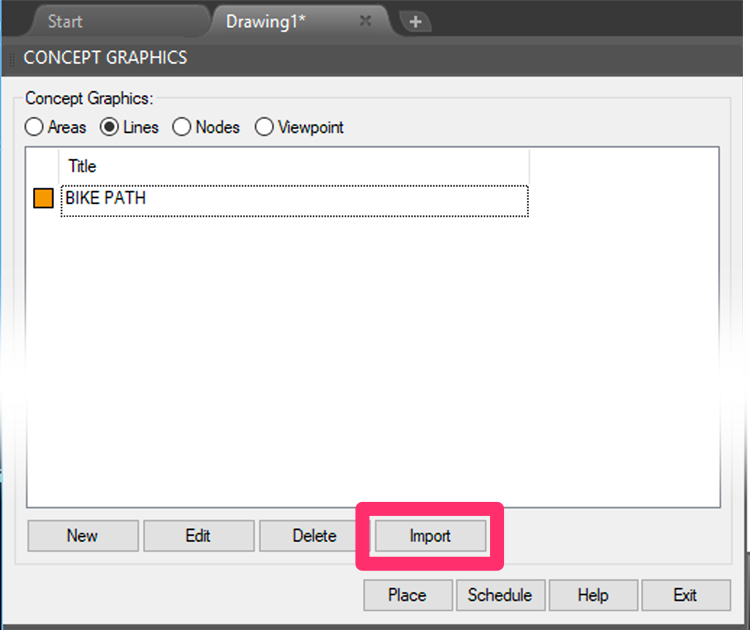
You'll need to repeat these steps for each category of Concept Graphics you want to import.
The Select Project dialog box will open.
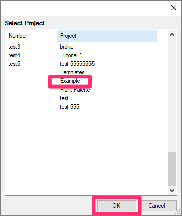
Select the template or project that includes the Concept Graphics you want to import.
Then click OK.
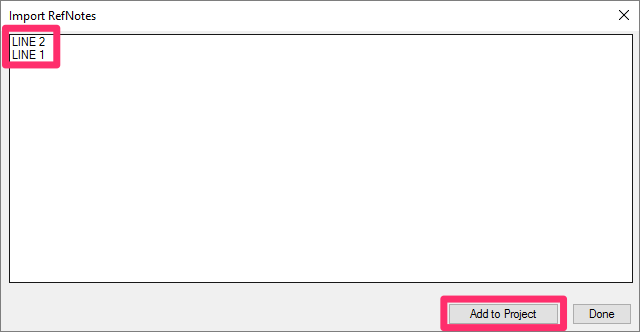
Select all the graphics from the selected category that you want to import from the selected project or template.
You can hold down the CTRL key (Windows) or the Command key (Mac) to select multiple graphics at a time.
Click Add to Project to add them to the current project.
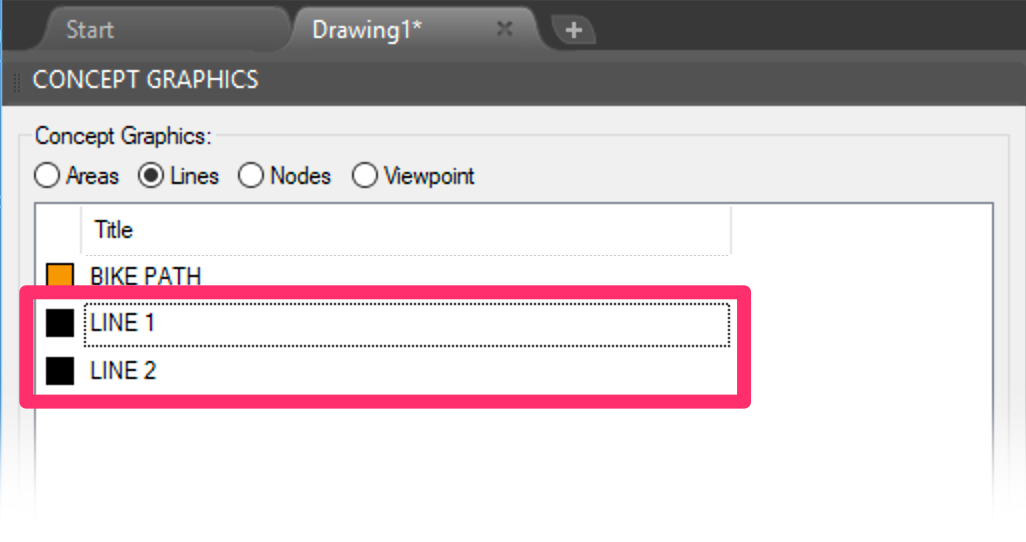
The Concept Graphics Manager will now include the Concept Graphics you've imported.
Those graphics, and all their data, are now added to your project, and you can place them as needed.
Repeat these steps for each Concept Graphics category you want to import.
Related Webinars
- Tools at Early Design: Learn how our Zoning and Concept Graphics tools can be used to illustrate the designer’s intent for a site, while working quickly within CAD, from nothing more than a satellite image. (1 hr 2 min)
- Concept Site Plan Tools: Conceptual design is an important preliminary step in any site design. We’ve made some recent improvements to our site concept tools that will make it even easier for you to develop an initial plan that lays out your design intent in a logical and clear way. (56 min)
- Streamlined Life Cycle of a Site & Hardscape Project: You have the tools at your fingertips – including our Concept Graphics tool – to take your site and hardscape design from concept to construction documentation, complete with quantities, data, callouts, and cost estimates. Learn a complete process spanning the life cycle of each project that will start cutting days off your overall drafting time. (1 hr 3 min)
Troubleshooting
Issue: CAD crashes or freezes in a drawing that contains concept lines and/or other gradients
Issue: You are experiencing a significant delay when attempting to add or place Concept Graphics
Issue: Bad DXF group (10) error when placing a Concept Graphic
Issue: Text in the Concept Graphics Schedule columns is overlapping
Issue: CAD freezes or lags after you place a Concept Graphics Schedule


