Site Dimensions
Quick video
- Site Dimensions Overview
- Pre-Setting a Dimension Style (DimStyle)
- Dimension Types
- Dimensioning in Your Details
- Changing the Units Shown in your Dimensions
- Dimensioning in Architectural Inches in a Decimal Feet Plan
- Related Webinars
- Troubleshooting
Our Site Dimension tools that allow for quick and accurate dimensioning of lines, angles, circles, and a number of other objects in your drawings.

Example of a Linear Dimension placed in a drawing
Looking for a way to place dimensions in your details? See our Detail Dimensions documentation.
The appearance of your Site Dimensions will vary depending on the Dimension Style (DimStyle) you have set. For more information, see our Dimension Styles (DimStyles) documentation.
See our dimensioning tools in action! Check out our Design F/X Overview webinar. The demonstration of our dimensionsing tools starts at 14:40 in the video.
Site Dimension Overview
The Site Dimension tools are available as:

Flyouts of the Dimension button on the F/X Site ribbon
A series of Command line commands:
- Site_Dim_Aligned (Aligned Dimension)
- Site_Dim_Linear (Linear Dimension)
- Site_Dim_Angular (Angular Dimension)
- Site_Dim_Arc (Arc Dimension)
- Site_Dim_Radius (Radius Dimension)
- Site_Dim_Diameters (Diameter Dimension)
- Site_Dim_Center (Center Mark Dimension)
- Site_Dim_Continue (Continue Dimension)
- Site_Dim_Baseline (Baseline Dimension)

Flyouts of the Site Dimension option on the F/X Site menu
Pre-Setting a Dimension Style (DimStyle)
Our dimensioning tools will only pull the dimension style (DimStyle) that is saved into the Land F/X system, or our default DimStyle if you haven't saved one in. If you have your own existing dimension standards, you’ll need to save that DimStyle into your Land F/X Preferences.
You can simply set your custom DimStyle to current and save it into the Preferences, but this practice can often result in issues with scaling. Instead, we recommend quickly re-creating your DimStyle starting with our default DimStyle. It’s easier than you think. See our DimStyles documentation for instructions.
Change the Arrowhead Style for Radius, Diameter, or Angular Dimensions
You may want to use different arrowhead styles for different types of dimensions. For example, you may want to use ticks for your Linear Dimensions but arrows for Radius Dimensions. For instructions, see our DimStyle arrowhead style documentation.
Dimension Types
Our Site Dimension feature encompasses several dimensioning tools.
Aligned Dimension
The Aligned Dimension tool allows you to place a linear dimension at an angle that is neither horizontal nor vertical – although this tool also allows for horizontal and vertical dimensions.
Open the Aligned Dimension tool:
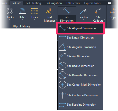
F/X Site ribbon, Site Aligned Dimension flyout
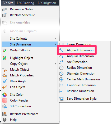
F/X Site menu, Aligned Dimension option
or type Site_Dim_Aligned in the Command line
This tool works in exactly the same way as the Linear Dimension tool, except it also allows you to either:
- Click to place a dimension manually, or
- Right-click to select an object to dimension

Placing an angular dimension manually

Selecting an object to dimension
Linear Dimension
Linear Dimensions measure the horizontal or vertical distance between two points, lines, or objects in your drawing.
If you need to dimension a line or object at an angle that is neither horizontal nor vertical, you'll want to use the Aligned Dimension tool.
Open the Linear Dimension tool:
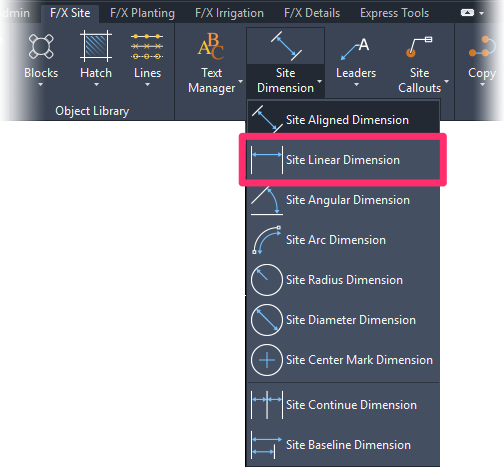
F/X Site ribbon, Site Linear Dimension flyout
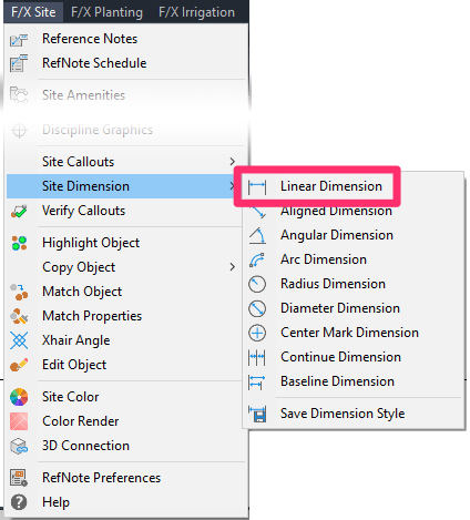
F/X Site menu, Linear Dimension option
or type Site_Dim_Linear in the Command line
You'll be prompted to Specify first extension line origin or <select object>.
You can either click to set the first of the two dimension lines or right-click to select an object to dimension.
If you click to start placing a dimension, you'll then be prompted to Specify second line origin.
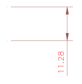
Click again to specify the other side of the dimension. You'll now see the dimension. You can then move the mouse horizontally or vertically and then click again to set the length of the dimension lines.
The example to the right shows a linear dimension measuring a vertical distance.
If you right-click to select an object to dimension, the cursor will turn into a pickbox. You can then select the object you want to dimension, then move the mouse and click again to set the length of the dimension lines.
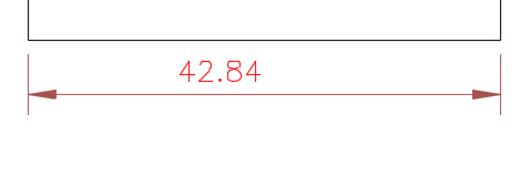
In this example, we've selected the horizontal side of a rectangle to dimension.
Angular Dimension
The Angular Dimension tool measures the degrees of an angle you select in your drawing.
Open the Angular Dimension tool:
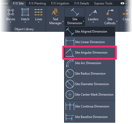
F/X Site ribbon, Site Angular Dimension flyout
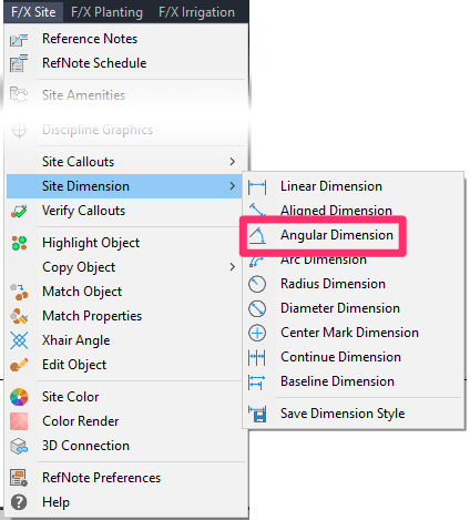
F/X Site menu, Angular Dimension option
or type Site_Dim_Angular in the Command line
You'll be prompted to Select arc, circle, line, or <specify vertex>.
Select an object you want to dimension in degrees. You can also right-click to set your own angle vertex manually.
If dimensioning an angle between two lines, you'll then be prompted to Select second line. Click to set the second line of the angle.

In this example, we'll place a dimension for an angle of 61 degrees between two lines.
Are your Angular Dimensions showing something else in place of the degrees symbol, such as a fraction?
You may need to adjust your Dimension Text style.

Arc Dimension
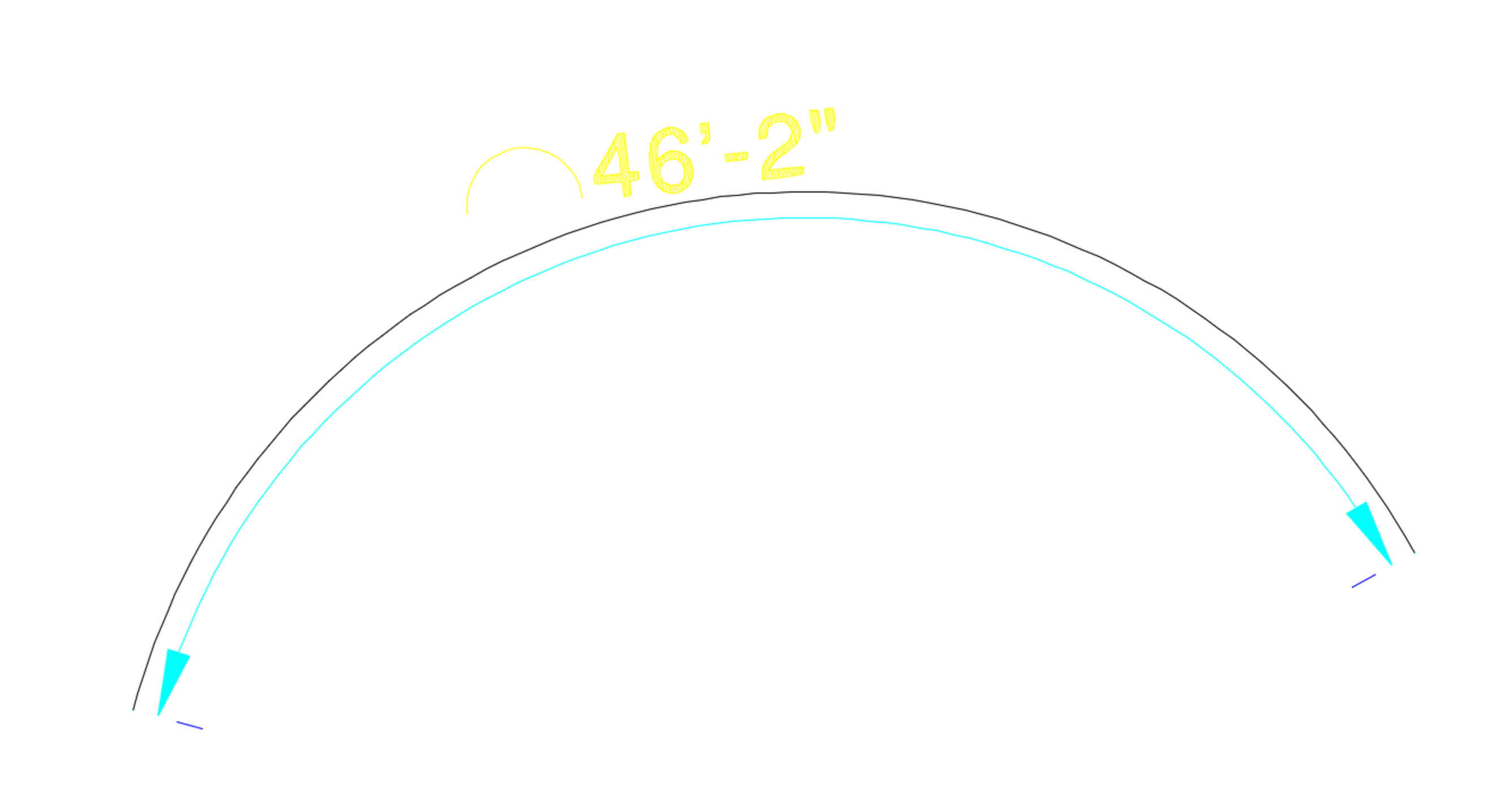
The Arc Dimension tool measures the length of an arc in your drawing.
Open the Arc Dimension tool:
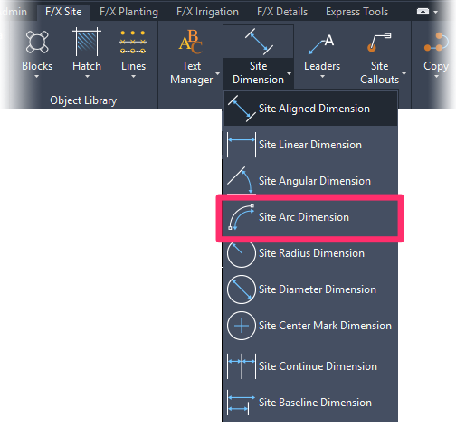
F/X Site ribbon, Site Arc Dimension flyout
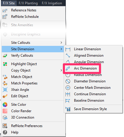
F/X Site menu, Arc Dimension option
or type Site_Dim_Arc in the Command line
You'll be prompted to Select arc or polyline segment. Select the arc you want to dimension.
Here's an example of an Arc Dimension measuring the length of an arc:
Radius Dimension
The Radius Dimension tool places a dimension of the radius of a circle or arc in your drawing.
Open the Radius Dimension tool:
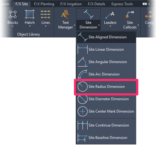
F/X Site ribbon, Site Radius Dimension flyout
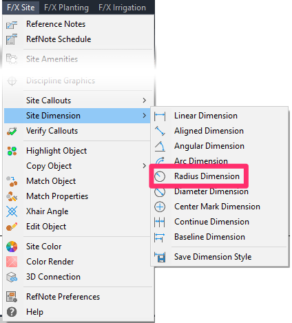
F/X Site menu, Radius Dimension option
or type Site_Dim_Radius in the Command line
Here's an example of a Radius Dimension measuring the radius of a circle:
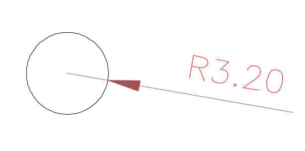
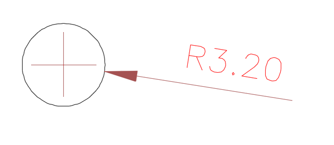
If you want, you can include a center mark in your Radius Dimensions, as pictured to the left.
Diameter Dimension
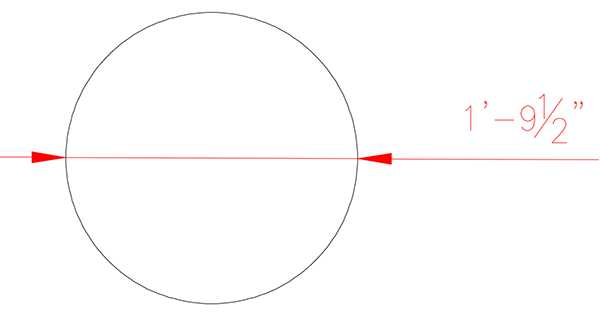
The Diameter Dimension tool places a dimension of the diameter of a circle or arc in your drawing.
Open the Diameter Dimension tool:
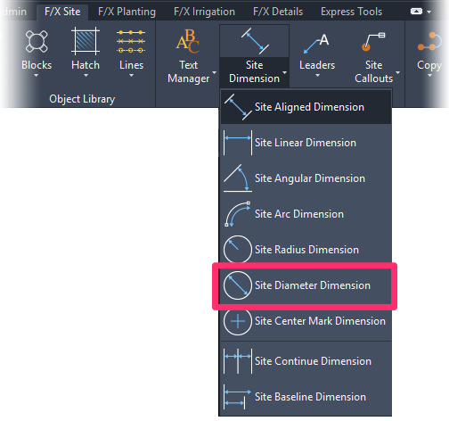
F/X Site ribbon, Site Diameter Dimension flyout
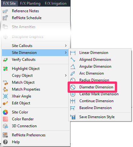
F/X Site menu, Diameter Dimension option
or type Site_Dim_Diameter in the Command line
Select a circle or arc, and click to place the diameter.
Center Mark Dimension
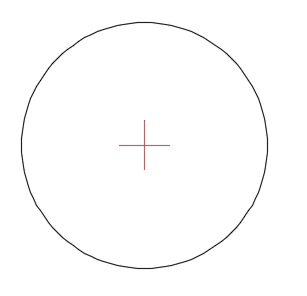
The Center Mark Dimension tool places a center mark within a circle or arc in your drawing.
Open the Center Mark Dimension tool:
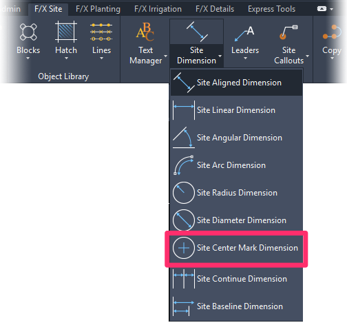
F/X Site ribbon, Site Center Mark Dimension flyout
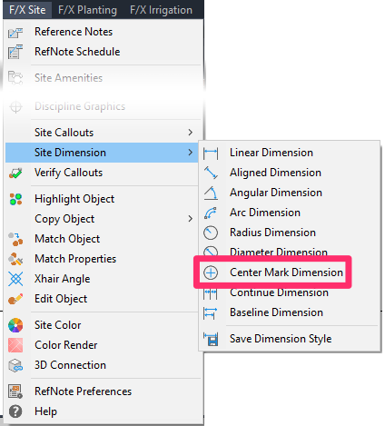
F/X Site menu, Center Mark Dimension option
or type Site_Dim_Center in the Command line
Select a circle or arc.
The center mark will be placed.
Continue Dimension
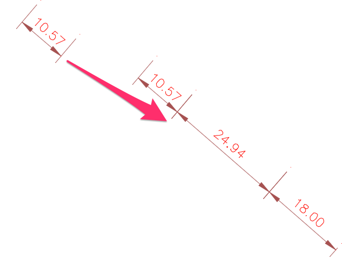
The Continue Dimension tool adds a dimension to the end of the last dimension placed (in other words, it continues that same dimension).
Open the Continue Dimension tool:
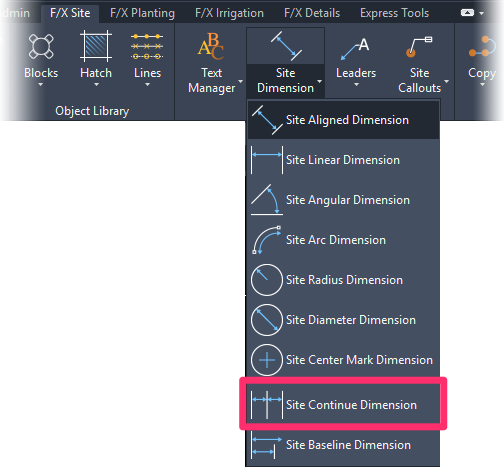
F/X Site ribbon, Site Continue Dimension flyout
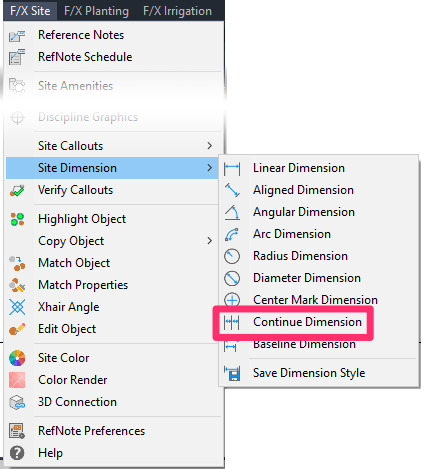
F/X Site menu, Continue Dimension option
or type Site_Dim_Continue in the Command line
In the example below, we'll use the Continue Dimension tool to add onto an existing Aligned Dimension of 10.57 feet.
p;
Baseline Dimension
The Baseline Dimension tool places a new dimension originating from the beginning (baseline) of the last dimension placed in your drawing.
Open the Baseline Dimension tool:
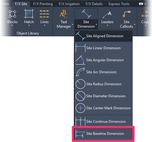
F/X Site ribbon, Site Baseline Dimension flyout
or type Site_Dim_Baseline in the Command line
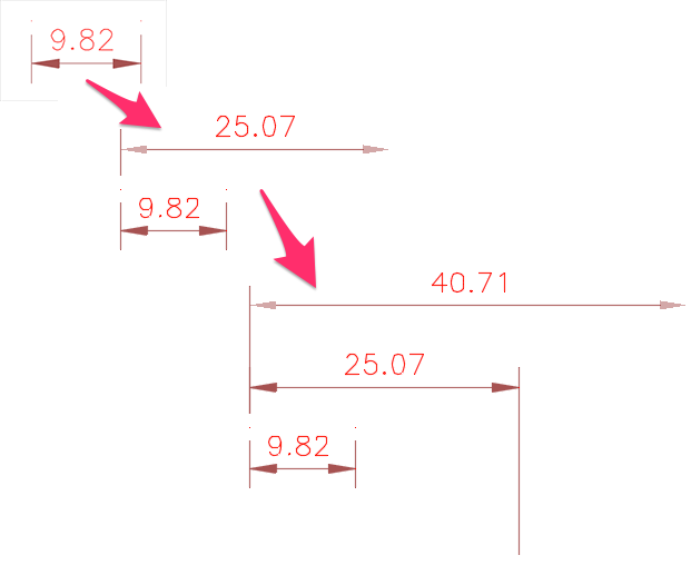
Baseline Dimension will latch a dimension onto the baseline of the last dimension placed. Click to place the new dimension. You can continue clicking to place additional baseline dimensions, or press Esc to end the function.
In the example to the right, we'll add a Baseline Dimension of 25.07 feet to an existing a Linear Dimension of 9.82 feet.
We'll then add a second Baseline Dimension of 40.71 by clicking again.
Dimensioning in Your Details
When placing tools in your details, make sure to use our Detail Dimensioning tools. Our Site Dimension tools are not designed to scale correctly within details.
Changing the Units Shown in Your Dimensions
In some cases, you might find yourself needing to place a dimension in Architectural Inches in a drawing where you're working in Decimal Feet, or vice versa. If this is the case, you can follow our instructions to:
- Change Dimension Units to Architectural Inches When Working in a Decimal Feet Drawing
- Change Dimension Units to Decimal Feet When Working in an Architectural Inches Drawing
Related Webinars
- Working With Dimensions in Land F/X: We show you all the necessary steps for setting up Dimension Styles (DimStyles) and saving them into Land F/X. We also provide some general practice tips and go over some common troubleshooting items. (1 hr 5 min)
Dimensioning in Architectural Inches in a Decimal Feet Plan
Some firms' standards call for placing dimensions in Architectural Inches (e.g., 6'-6") in a plan where the units are set to Decimal Feet (e.g., 6.5'). Instructions >
Troubleshooting
Issue: You want your radius dimensions to include a center mark
Issue: Angular Dimensions do not include degrees symbols
Issue: Dimensions are being displaced, moving, or going off into space after you detach an Xref
Issue: Your dimensions are showing incorrect lengths even though your scale and units are set correctly
Issue: Your dimensions are not showing up in Paper Space
Issue: The text in your Site Dimensions is appearing scrunched, pushed together, or overlapping
Issue: Dimension is exploded when placed, and the number becomes a slash


