Editing Our Default Irrigation Symbols
- Editing the Lineweights in Our Irrigation Symbols
- A Few Tips for Editing Our Symbols
- Locating and Reviewing Our Irrigation Symbol Files
- Editing the Coverage Radius for One of Our Symbols
- Changing Our Irrigation Symbol Lineweights Using BatchMan (Advanced)
- Creating a Preview Slide
- Re-Creating Your Custom Irrigation Symbols Using Our Default Blocks
- Changing the Symbols for Irrigation Equipment in Your Projects and Drawings
- Creating a Custom Symbol Family for Existing Equipment
- Related Webinars
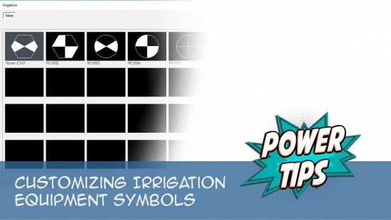
After reviewing the plotted drawing of our irrigation symbols (see link below), you may decide that you want to make minor edits to them. For example, some of the lineweights for spray or rotor heads, valves, equipment, etc., may be too thick or too thin for your standards.
Each of our symbols is simply a block that originates from the linework in a separate DWG file within our Irrigation Symbol Library. The most logical approach to altering our irrigation symbols is to open its drawing file and make changes as necessary. The irrigation symbols are located in several folders within the LandFX/Blocks/Graphics/Irrigation folder.
Our Irrigation Symbols Drawing
We've compiled all our irrigation symbols into a single drawing for your review, linked below. To download this drawing, right-click the link below and select Save Target As or Save Link As from the menu. Open this drawing and TURN ON ALL LAYERS to review all the irrigation symbols LandFX uses in the system. You can also plot the drawing using the LandFX.CTB plot style, or your office's CTB file. This will allow you to review the symbols as they plot.
Looking to add your own spray symbols to the system? See our Adding Your Spray Symbols documentation.
For more information on our irrigation symbols, we encourage you to download and review our Irrigation Getting Started Guide.
Editing the Lineweights in Our Irrigation Symbols
Quick video
In CAD, lineweight is tied directly to layer color. As with any lineweight changes you need to make in our blocks, in the vast majority of cases you can simply follow our steps to Convert our Line Colors to your office standard. Our irrigation blocks use only a small handful of layers and colors, and you should be able to make those very simple edits from the General Preferences.
An Example
We use the color red quite commonly throughout our library of irrigation symbols, and we have red printing at 0.25 mm in our LFX.ctb file. If you have red printing at a different thickness, you'll need to move our red to one of your colors that prints at 0.25 mm (or designate an additional, unused, color to print at 0.25 mm). So once you decide on that new color, you would go to the General Preferences, click Block Color, select Color 1, edit it, and select the new color it should change to.
Let’s say, for example, that you've decided to designate Color 30, which you don’t use in your CTB currently, to now print at 0.25 mm. So you select that color and edit your CTB to reflect that change. For a proper test, delete and purge out all irrigation symbols (or start a fresh drawing), and confirm that the color red has been converted to Color 30 when you insert a symbol.
Most Irrigation F/X users will find our steps to convert the line colors sufficient for fine-tuning the lineweights within the irrigation symbols. In extremely rare cases, an office may have a standard that necessitates changing the layer colors in only the irrigation symbols. To do so, you can follow our steps to change the symbol lineweights using our BatchMan tool.
A Few Tips For Editing Our Symbols
Quick video
We've invested a great deal of time and effort into developing our vast symbol library. In most cases, our symbols should be sufficient to represent irrigation equipment you place in your drawings. If your office needs to adhere to an established standard for spray symbols, you are free to add your symbols to our library – a very specific process that involves copying the linework from each of your symbols into an existing drawing file within our existing symbol folder structure.
Our symbols are automatically scaled for Model Space, so they will be drawn to the size at which they will appear when plotted (or how they will appear in Paper Space).
The insertion point is located at or near the center of the symbol, and should remain so.
We recommend keeping the layer naming convention similar.
With many of the symbols, the text in the symbol is an attribute. You can change the font style as desired, but we recommend not deleting it unless you add another attribute to replace with the same Tag, Prompt, and Value.
Locating and Reviewing Our Irrigation Symbol Files
The blocks for our irrigation symbols are located in the folder LandFX/Blocks/Graphics/Irrigation within the following subfolders:
- Bubbler: for bubbler symbols.
- Drip: for drip emitters, drip valves, etc.
- Equipment: for auxiliary equipment other than heads or valves, such as controllers, flow sensors, etc.
- Rotor: for rotors and rotator heads.
- Schedule_Symbols: for the schedule blocks that will group heads into a schedule.
- Spray: for all the spray head families.
- Valve: for remote control valve, quick couplers, etc.
You may want to change only certain symbols, such as spray heads only. In this case, you can use BatchMan on only the subfolder that contains the spray head symbols.
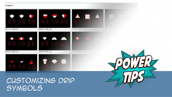
Editing the Coverage Radius for One of Our Emitter Symbols
You may want to edit or change the size of a coverage block, or radius block, for an emitter symbol.
The coverage, or radius, block, shows the coverage that will be achieved by a given head. You may want to the radius larger or smaller, for example.
To make changes to a coverage radius of one of our emitter symbols, follow our steps to edit the coverage block of a head.
Changing Our Irrigation Symbol Lineweights Using BatchMan (Advanced)
Most offices can adjust the lineweights within our irrigation symbols to meet their standards by following our steps to change our line colors. In the extremely rare case that you need to fine-tune the lineweights in only the irrigation symbols, you can do so with the help of our BatchMan tool. We've provided the steps below in response to a scattered few user requests, but we highly recommend changing the line colors from the General Preferences instead.
If necessary, you can use our BatchMan tool to change the lineweights on all the irrigation blocks in any one folder at one time – or in all folders containing irrigation symbol blocks.
Open BatchMan :

F/X Admin ribbon, BatchMan button
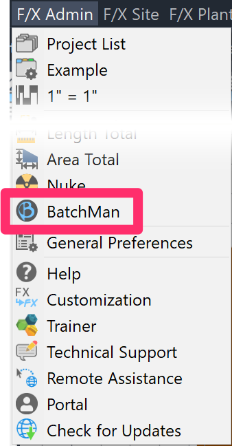
F/X Admin pull-down menu
or typeBatchMan in the Command line
At this point, you'll need to decide whether you want to select only the blocks in a certain folder or folders, or whether you want to change the lineweights in all the irrigation folders at once.
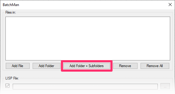
The BatchMan dialog box will open.
Click Add Folder + Subfolders.
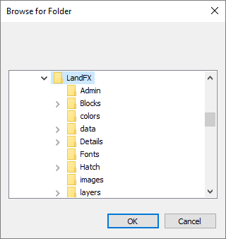
In the Browse for Folder dialog box, navigate to and select the folder containing the symbols whose lineweights you want to change.
Click OK when finished.
If you decide to change the symbols in all the irrigation symbol folders at once, navigate to the folder LandFX/Blocks/Graphics/Irrigation.
Back in the BatchMan dialog box, a list of all files in the folder you selected will now appear in the Files in: pane.
- Check the box next to Layer Names and Colors.
- Under Save As, select the option for the version of CAD you'd like to use when saving your edited symbols.
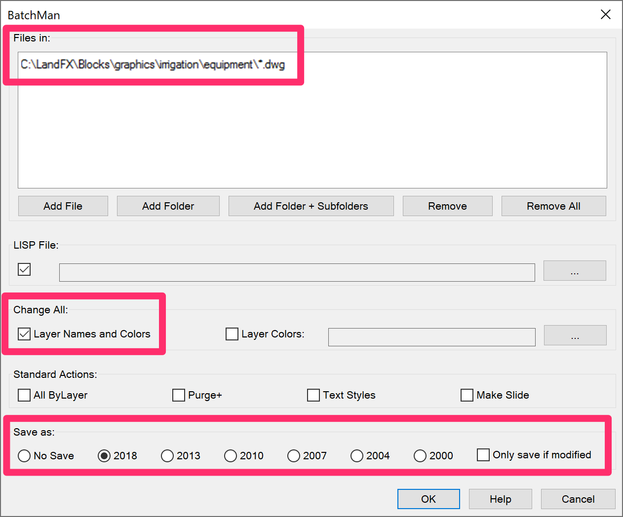
Click OK to change layer names or colors in the symbol files within the folder you've selected. Allow a few minutes for BatchMan to compile the symbol files.
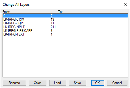
The Change All Layers dialog box will open.
Here, you'll see a list of all layer names and colors in the files you've selected. Our lineweight convention is to list the lineweight by millimeters in the name of the layer – for example, 013M represents 0.13 mm.
Highlight the name of a layer you want to edit, and make your changes, as described below.
Changing a Layer Name
To change the name of a layer, select it and click Rename.
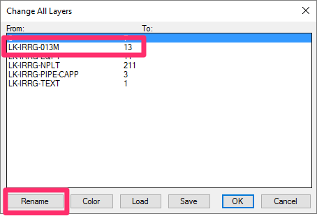

Enter a new name for the layer in the New Layer Name dialog box, then click OK. (In this case, type the name of an existing layer that has your desired lineweight.
Changing a Layer Color
To change the color of a layer, select it and click Color.
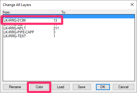
Select a new layer color in the Select Color dialog box, then click OK. (In this case, select the color of an existing layer with your desired lineweight.)
Creating a Preview Slide
If you edit a symbol or symbol family, you may need to create a preview slide to be able to see your new version when you go to select symbols. Here's how:
1. Zoom in as closely as possible on a few of the equipment symbols in the family you edited.
2. Type MSLIDE in the Command line.
3. You'll be brought to the Create Slide File dialog box. Save the slide to the same subfolder where you saved your edited symbols.
The slide will be saved as an SLD (.sld) file. Give it the same name as the existing slide for the symbol family you just edited, and save your new slide over it.
Remember to match the aspect ratio of the target image as closely as possible with your display window. So for instance, if your AutoCAD window is spanning two monitors, the resulting slide could have an aspect ratio of 8:3, while the one in the dialog is 4:3, which will result in it not being zoomed in enough.
Re-Creating Your Custom Irrigation Symbols Using Our Default Blocks
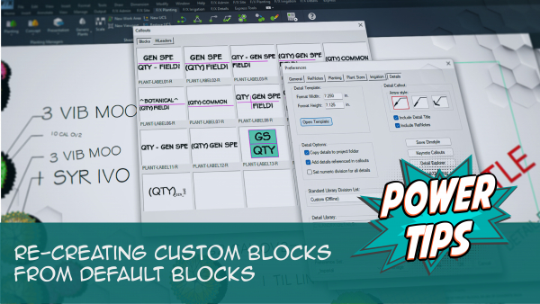
Has something gone wrong with any of your custom irrigation symbol blocks? We recommend using our default blocks as a basis for your custom blocks, as they're already set up correctly for best performance in CAD. Use them to repair or re-create your custom blocks.
See our Re-Creating Custom Blocks from Default Blocks Power Tip, linked to the right, for more information and instructions.
Changing the Symbols for Irrigation Equipment in Your Projects and Drawings
If you've already added a particular irrigation component to your project – even if you've already placed that equipment in a drawing – you may want to change its symbol to your custom version. The method of changing out the symbol varies slightly between equipment types (different types of heads, drip emitter areas, valves, etc.). See our documentation on changing symbols for irrigation equipment.
Creating a Custom Symbol Family for Existing Equipment
When creating an irrigation plan for a site where existing equipment is already installed, you may want to create extra visual separation from the proposed irrigation on your plan. Here's how.
Related Webinars
- Irrigation Customization: We cover the Irrigation Preferences, including what to consider as you’re setting up your office standards, and what will and won’t change on the fly when you modify these settings, as well as customizing irrigation symbols. (1 hr 2 min)
- Dotting Your Irrigation I's: Each client will have different styles and requirements, but the concept is the same: You should feel comfortable matching any client’s standards. We'll show you how. (1 hr 1 min)
- Customizing Irrigation – What You Should Know: Join us for a discussion on the "need-to-knows" of making the software work with your office standards. We'll show you the different ways you can customize, and you'll pick up some valuable tips for setting up the software to meet your office standards. (1 hr 1 min)
- Implementing Your Office CAD Standards: Find out how easily you can adapt your own office standards to Land F/X – and how effectively the software will then apply them to your projects. (1 hr 2 min)
- Working With Blocks: Take a broad look into the role of blocks within Land F/X and how to integrate your personal set of blocks into our system. (1 hour 4 min)


