Valve-in-Head (VIH) Rotors – Considerations, Piping & Sizing
- VIH Rotors Overview
- Adding and Placing VIH Rotors
- Piping to VIH Rotors (Draw Lateral Pipe Tool)
- Sizing the Pipe Connecting VIH Rotors (Size Mainline Tool)
- Other Important Considerations
- Changing the Symbols for VIH Rotors in Your Projects and Drawings
- Related Webinars
A valve-in-head (VIH) rotor is exactly what it sounds like: a rotor head that also includes a valve. This type of valve/emitter hybrid allows for a system that requires large volumes of water delivered with a high level of control. For this reason, VIH rotors are especially valuable (if not essential) in larger water applications such as athletic fields and golf courses.
Because they include valves, VIH rotors will require you to take a few important considerations into account when you use them in your systems. As such, our software treats them somewhat differently from normal heads. For example, you'll pipe to them using our Draw Laterals tool but size them using our Size Mainline tool.
For further information about golf course design and its specific requirements, see our Golf Course Irrigation page.
VIH Rotors Overview
Because they include valves, VIH rotors can handle pressurized pipe – a must for systems that require stations that deliver higher volumes of water. Many designers refer to these inner sections of pipe as "laterals" (even though they're constantly pressurized, and therefore are technically mainlines) and the outer mainline loop as the "feeder mainline" to differentiate between the two.
This pipe that connects VIH rotors to each other is, for all intents and purposes, mainline. It's constantly pressurized to allow for high volume. When installed, it's often the same pipe as that used in the outer mainline loop.
However, this pipe also acts like lateral pipe, in that it delivers water to heads. Stations employing VIH rotors are commonly fed by shut-off valves (AKA isolation valves) – especially in golf course design – which allows the entire station to be turned off for maintenance. This type of design makes it possible to specify a pipe class for this pipe that would typically be used as a normal lateral line (such as a cheaper PVC pipe). So really, it's the best of both worlds: a pipe that's pressurized but that is also easily replaceable.
Adding and Placing VIH Rotors
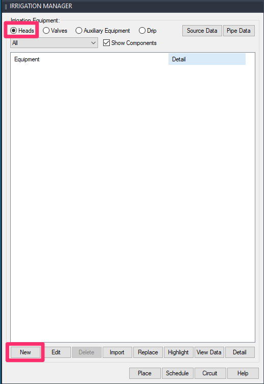
You can add VIH rotors to a project in the same way you'd add any other head: select the Heads option in the Irrigation Manager and click New.
Select your manufacturer and performance data, and add the rotor to your project.
As mentioned above, many designers choose to spec a smaller VIH rotor (such as 1 1/2 inches) to accommodate a smaller pipe diameter.
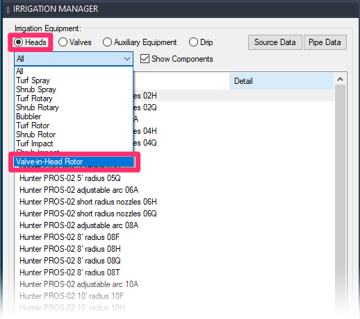
Our equipment menu for heads includes a Valve-in-Head Rotor option, which allows you to find your VIH rotors quickly once you've added them.
To begin placing a VIH rotor, highlight it and click Place.
You can also use our Place Rotor tool to place VIH rotors on the fly. See our Placing Rotors section for more information.
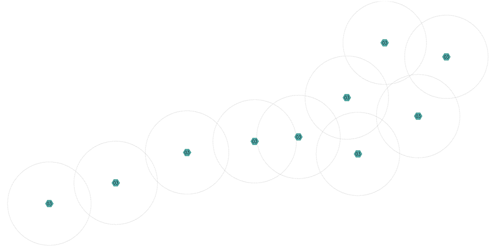
Here's an example of several VIH rotors placed throughout a golf hole:
Piping to VIH Rotors (Draw Lateral Pipe Tool)
When you're ready to pipe to your VIH rotors, use our Draw Lateral Pipe tool.
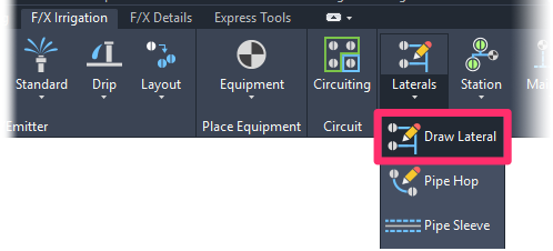
The result will be a pipe that will look like laterals in your drawing to differentiate it from the outer ("feeder") mainline, but the system will still size and treat it like mainline.
With Draw Laterals active, connect your VIH rotors as you would any other head. Here's our golf hole with piped rotors (note that the line representing the pipe is solid, denoting a lateral line):

One advantage of representing this pipe as lateral pipe in our system is the ability to group several VIH rotors into a station for organizational and error-checking purposes.
Note that you'll also use the Draw Lateral tool to pipe between the VIH rotors in your station and any valves that are feeding that station. In this example, we've placed a shut-off valve – a common feature in golf course irrigation – and piped it to our station using lateral pipe.
The valve is connected to the mainline loop with mainline pipe.
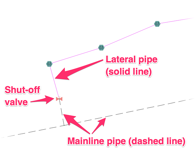
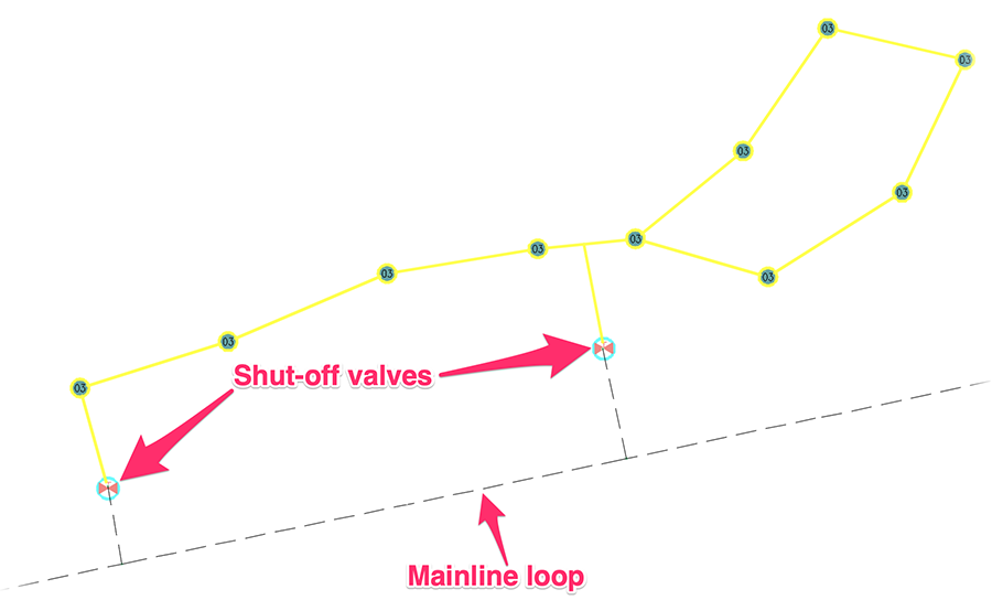
In the image below, we've completed our station of VIH rotors and piped it to two shut-off valves.
Note that when we use the Highlight Station tool, it highlights the station only up to the shut-off valves.
Sizing the Pipe Connecting VIH Rotors (Size Mainline tool)
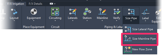
When you're ready to size the pipe connecting your VIH rotors, take care to use our Size Mainline tool – even though you drew it as laterals and it looks like laterals.
The Size Mainline tool will recognize that this pipe is pressurized mainline, and will size it to allow for the pressurization that characterizes mainline pipe.
Other Important Considerations
Because VIH rotors include valves, and because the pipe you use to connect them acts like mainline, you'll need to take a few other considerations into account:
- Use our Verify Mainline tool to check for errors in the pipe connecting your VIH rotors. Any piping errors will be related to potential issues that affect mainline, rather than lateral, pipe.

- Want to use quick-coupler valves? No problem. Although lateral line usually can’t handle quick coupler valves, this one will handle it just fine because the system treats it like mainline. Just place your quick-coupler valves and pipe to them from your VIH rotor station using our Draw Lateral Pipe tool.
-
Because VIH rotors include valves:
- You can – and should – use our Valve Callout tool to label them. They'll receive numbers as would any other valve.
- They'll be listed in any Valve Schedule you place in your drawing.
Changing the Symbols for VIH Rotors in Your Projects and Drawings
If you've already added a particular VIH rotor to your project – even if you've already placed it in a drawing – you may want to change its symbol to another one of our default symbols, or a version you've created. See our documentation on changing symbols for irrigation heads.
Related Webinars
- Golf Course Irrigation: We'll demonstrate some of the great tools Irrigation F/X offers to help ensure proper mainline sizing and scheduling. We'll also discuss the use of using flow zones, shut-off valves, and valve-in-head rotors. (1 hr 4 min)


