Slope Callouts & Slope Areas
Quick video
- Slope Callout Overview
- Place an Arrow Point Manually
- Select a Slope Dimension Line
- Select Two Spot Elevation Callouts
- Slope Areas
- Correcting Scale With Slope Callouts
- Troubleshooting
You can use our Slope Callouts tool to place callouts that show the direction and percentage or ratio of slopes in your drawing. You can also use this tool in conjunction with our Spot Elevation tool to call out the slope between two existing elevations.
In addition, we've built the Slope Area feature into this tool. With Slope Areas, you can apply a specific slope to closed polyline regions in your drawing. Any smart objects (such as plants, RefNotes, or irrigation equipment) represented by hatches that lie within Slope Areas will be recalculated to reflect the slope.
Slope Callouts are related to Spot Elevations. For more information, see our Spot Elevation documentation page.
Slope Callout Overview
Open the Slope Callout tool:
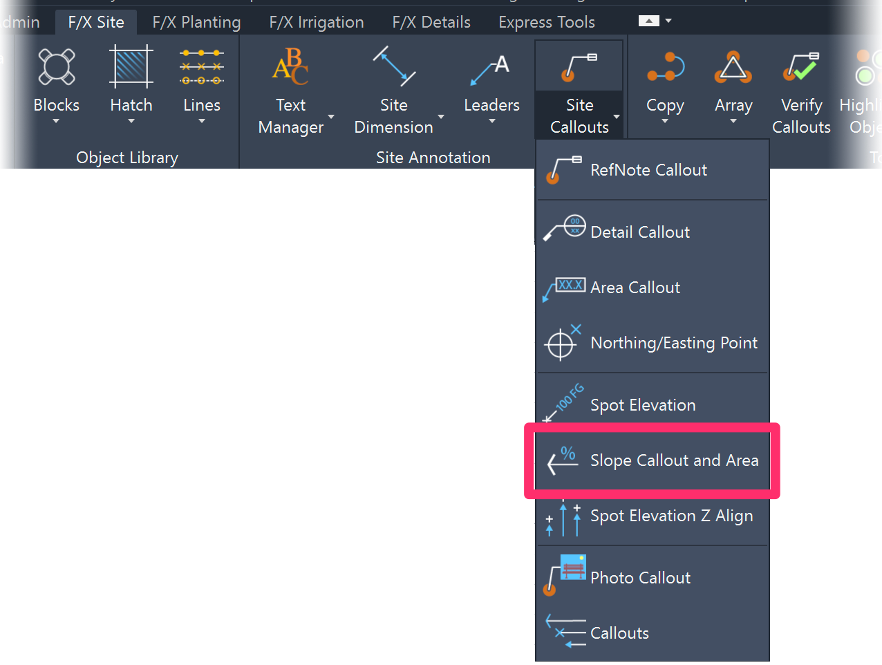
F/X Site ribbon, Slope Callout and Slope Area flyout

F/X Site menu, Slope Callout and Area option
or type FX_PlaceSlopeCallout in the Command line
The cursor will turn into a pickbox. The Command line will prompt: Arrow Point, or select slope dimension or first spot elevation.
You have several options at this point:
- Place an Arrow Point Manually
- Select a Slope Dimension Line
- Select Two Spot Elevation Callouts
- Create a Slope Area
Place an Arrow Point Manually
To place an arrow point manually, just click to place the callout arrow. You can then use the mouse to orient the callout, and then type the slope percentage in the Slope dialog box.

Select the arrow point location, then adjust the orientation of the Slope Callout.
Type the slope percentage in the dialog box.


The Slope Callout will be placed.
Select a Slope Dimension Line
The cursor will turn into a pickbox when you open the Slope Callout tool. Use the pickbox to select one of the slope dimension lines that appear when you place Spot Elevations in relation to each other.
Use the pickbox to select an elevation "dimension line."


A callout of that slope will appear along the line.
Because the dimension line is non-plot, it won't show up when you plot.

Select Two Spot Elevation Callouts
Quick video
You can also pick two Spot Elevation callouts. A Slope Callout will appear between the two Spot Elevation callouts with the percentage of slope indicated for these elevations.
Use the pickbox to select the text portion of first Spot Elevation callout. Then select the text portion of the second Spot Elevation callout.
The Slope Callout will be placed between the two.

When selecting two Spot Elevation callouts, make sure you select the text portions of the callouts. Otherwise, the Slope Elevation callout will come in blank.
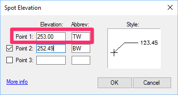
When calculating a slope, note that if you select a Spot Elevation callout that lists multiple elevations, the system will use the Point 1 elevation for the calculation.
Slope Areas
A Slope Area takes the grade percentage or ratio of an existing Slope Callout and applies it to a closed polyline area in your drawing. Objects represented by any smart hatches within that polyline will have their quantity, volume, or area recalculated based on the slope.
You can either draw Slope Areas on the fly or select the boundary of an existing smart hatch to convert it into a Slope Area. This feature can be applied to smart hatches representing objects such as:
- Groundcovers and Shrub Areas
- Area or Volume Reference Notes (RefNotes)
- Dripline irrigation areas
How Slope Areas work:
A region's slope directly affects the amount of actual ground covered by that region. For example, if you have two regions – one sloped and one flat – that appear identical in size and shape from plan view, the sloped region will always be larger. When you create a Slope Area, all smart hatches (not blocks) within it will be recalculated to account for increased square feet or meters resulting from the slope percentage or ratio in that area, usually resulting in a larger quantity or amount. In the case of dripline areas, the flow will also be adjusted according to the increase in dripline and emitters.
Note that Slope Areas will not affect drip emitter areas, pipe lengths, or anything represented by blocks, such as individual trees or shrubs, site amenities, or irrigation components aside from dripline areas.
To create a Slope Area, open the Slope Callout tool. The cursor will turn into a pickbox. Use this pickbox to select an existing Slope Callout you want to use in creating the area. The percentage or ration expressed by that callout will be applied to the entire Slope Area.
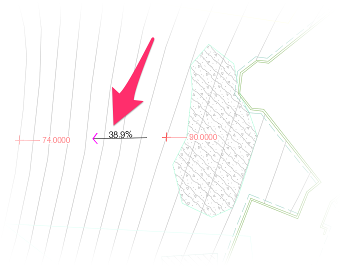
In this example, we'll select an existing Slope Callout showing a slope percentage of 38.9%.
After selecting a callout, you'll be prompted in the Command line to Select polyline, or [Draw]:
You can either select an existing polyline area in your drawing to convert it into a Slope Area, or type D to draw the Slope area on the fly. In our example, we'll type D and then draw a closed polyline area that will become our Slope Area.
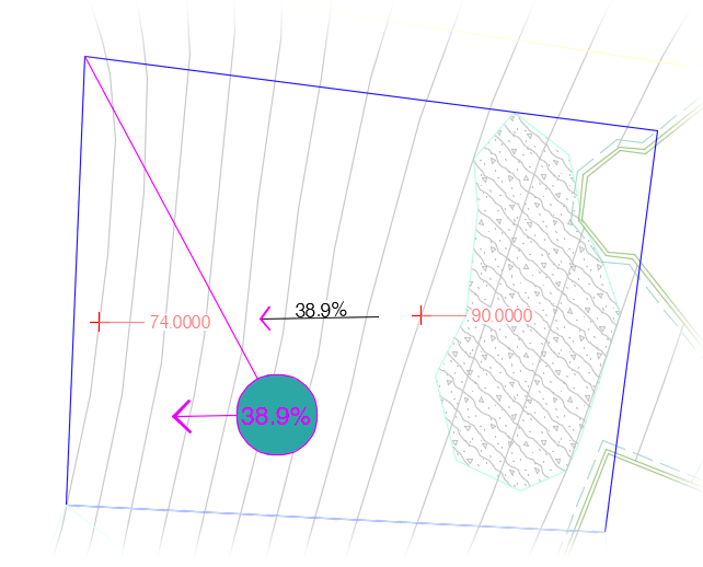
After you've selected or drawn your closed polyline, it will convert into a Slope Area and will contain a Slope Area Callout indicating the slope that is now applied to the entire area. The callout will mimic the slope direction of the Slope Callout you selected while also showing its same slope and will insert at the geometric center of the Slope Area.
In our example, the 38.9% slope expressed by the Slope Callout we selected will now apply to the entire Slope Area. For example, the plants in the groundcover hatch within the area will now be recalculated based on that slope when we label those plants or place a Plant Schedule.
Note that Slope Area Callouts will be nonplot by default, meaning they won't show up when you plot your drawing. If you want to see these callouts in your plotted drawing, you can select them and either change their layers to plot or move them to layers that are set to plot.
How Slope Areas Interact With Other Land F/X & AutoCAD Tools
We've integrated Slope Areas into a number of other Land F/X tools in the following ways:
- Highlight Plant and Highlight Object: These tools will only highlight Slope Areas consisting of smart Land F/X objects such as plants and Reference Notes.
- Scheduling tools: If you run any of the following schedule in a drawing that includes one or more Slope Areas, the scheduling tool will scan all smart hatched areas relevant to that schedule to determine whether they are inside a Slope Area. If so, the square footage/meters making up those areas will be recalculated, along with (in most cases, except where noted below) any relevant quantities or rates based on slope factor. These include:
- Plant Schedule: Groundcovers and Shrub Areas
- Concept Plant Schedule: Concept Plant areas
- Concept Graphics Schedule: Concept Graphic Areas, including Site Development hatches
- Reference Notes (RefNotes) Schedule: Area/Volume RefNote hatches
- Irrigation Schedule: Schematic zones, Areas for Dripline, and Areas for Drip Emitters. Note: For Areas for Drip Emitters, only the square feet/meters and equipment quantity will be recalculated.
- Valve Schedule and Watering Schedule: Schematic zones and Areas for Dripline
- Runtime Schedule: Will only consider the overall flow adjustments based on slope that will affect runtime calculations
- Critical Analysis: Schematic zones, Areas for Dripline, and Areas for Drip Emitters. Note: The Critical Analysis will change the total square footage/meters of these items to be applied to pressure calculation.
- Plant and Concept Plant Labels (Group, Single, Connecting Line, and Connecting Arc): Groundcovers and Shrub Areas. Concept Plant labels will also check Concept Planting areas such as seed and grass mixes. Note: Group labels can potentially include plants in multiple areas within different slopes.
- Verify Labels for plants: If any groundcovers or Shrub Areas are within a Slope Area,the tool will change the plant quantity calculation of those areas to include slope factor, which may change an existing label if the Slope Area has changed or was added after the label was placed. Note: Group labels can potentially include plants in multiple areas within different slopes.
- Valve Callouts: All Areas for Dripline to recalculate flow rates
- Planting areas: A Slope Area will recognize a planting area if at least 51% of the planting area vertices lies fully inside the Slope Area boundary. Vertices of a planting area exactly on the Slope Area boundary count as being outside the Slope Area.
Slope Areas also apply to:
- Match Object, Match Plant, and Match Equipment: If you select a Slope Area callout or boundary as a source object with one of these tools active, the duplicate area you place will also become a Slope Area.
- User Coordinate System (UCS): When a tool scans for whether an area is within a Slope Area, the scan will be compatible with any UCS that's been set in the drawing.
- External References (Xrefs): Schedules will recognize Slope Callouts in Xrefs, as long as the Xref is on the layer L-SLOPE-AREA and the schedule is configured to include Xrefs. Schedules configured to include Xrefs will also recognize Slope Areas in the live drawing even if the objects calculated by the schedule (such as plants) are in an Xref.
- Area Callouts: If you run the Area Callout tool and select a hatch or polyline inside a Slope Area, the area will be calculated based on the slope.
- Area Total: Area calculations will account for closed polylines within a Slope Area.
Customizing Slope Area Callouts
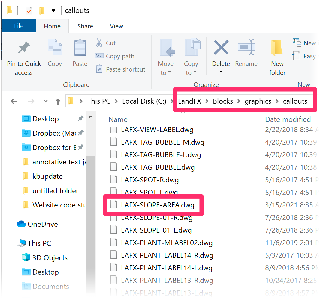
Slope Area Callouts look like the one pictured above by default. If you want to customize their appearance, you can edit their source files in the folder LandFX/blocks/graphics/callouts.
You'll only need to edit one source file per measurement system. The source file for Imperial Slope Area callouts is named LAFX-SLOPE-AREA.dwg. If you use the metric system, the block will be named LAFX-SLOPE-AREA-M.dwg.
Keep in mind that Slope Area callouts are non-plot by default and, as a result, won't appear in your plotted drawing. You'll only need to edit them if you want to change their appearance in your drawing file as viewed in CAD, or if you plan to put them on plot-designated layers so they show up in your plotted drawing.
Correcting Scale With Slope Callouts
If your Slope Callout text is coming in too big or too small in relation to the rest of your drawing, you're most likely facing a scaling issue. If this is the case, follow our steps to correct scale in callouts.
If you want to make permanent changes to the size or scale of the entire Slope Callout as it inserts in your drawings, you can do so by editing the Slope Callout source blocks.
Related Webinars
- Simple Site Layout and Grading Tools: Our Civil and Survey Manager (formerly known as the Grading Manager) includes some easy-to-use tools designed to help you lay out a plan in AutoCAD with Northing/Easting points, Spot Elevations, and Slope Callouts. We'll go over a few basic examples showing how these tools work, and provide some tips on how to incorporate them into your construction documentation workflow. (58 min)
- Grading A, B, C for Landscape Architects: Follow along as we cover the basics of simple landscape grading. We cover some simple concepts like calculating slope and interpolating contours, and show you how to use our easy grading tools in a real plan. (1 hr 4 min)
- Common Land F/X Questions: This webinar covers some of our lesser-known tools, including our Spot Elevation tool and how it relates to Slope Callouts. (1 hr)
- Grading and Drainage: Learn simple grading processes using our annotation tools, as well as some basics in Civil 3D for more dynamic site modeling. We'll explore how to automate your grading workflow based on the needs of the project. (1 hr 2 min)
- Site Plans and Land F/X: Aaron Emerson of Mills Design Group will show some award-winning case studies of how the Land F/X Site tools, including the grading tools, are used throughout his office. Aaron will also go over some important lessons learned while setting up an efficient site design workflow. (57 min)
Troubleshooting
Issue: Spot Elevations and/or Slope Callouts are oriented incorrectly or pointing in the wrong direction
Issue: Slope Callouts are coming in blank
Issue: Your Slope Callout arrows are hollow, not solid, or displaying as lines only
Issue: You received an Invalid Input error when attempting to place a Slope Callout


