Adding and Placing Valves
Quick video
Our valve symbols download on demand. If you go to place a valve, the symbol should download as necessary.
You can also have the system download all irrigation symbols from the Check for Updates feature if you'd like.
Adding Valves to a Project
Open the Irrigation Manager:

F/X Irrigation ribbon, Irrigation button
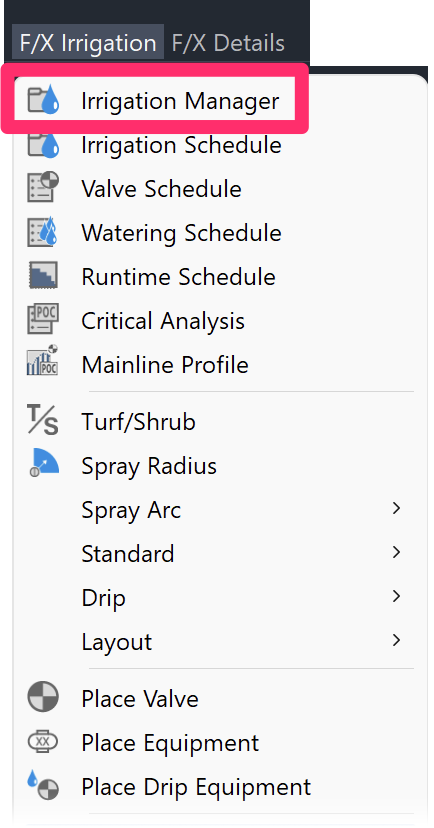
F/X Irrigation menu, Irrigation Manager option
or type ProjectIrrigation in the Command line
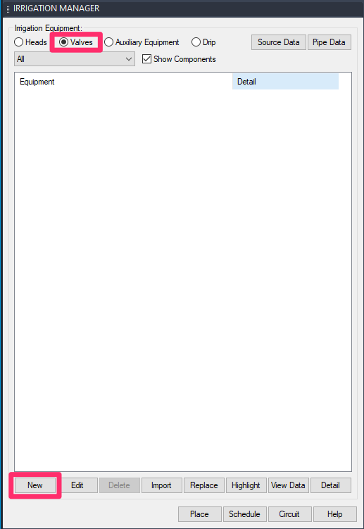
The Irrigation Manager will open. Select the Valves option, then click New.
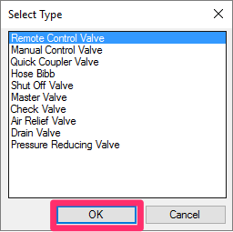
Select the type of valve you want to add, then click OK.
You'll now see a list of all manufacturers offering the selected valve type in our equipment database.
Select a manufacturer.

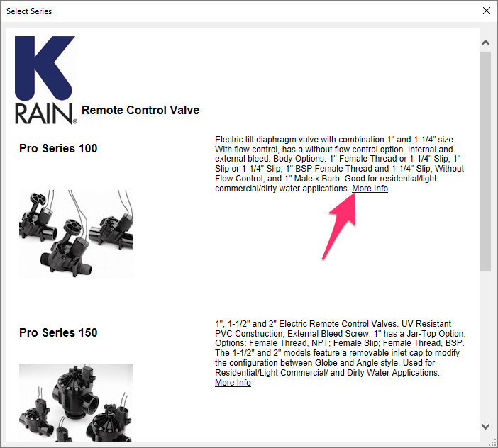
You'll now see a list of all series of the selected valve type offered by the selected manufacturer in our database.
Click a series to select it.
You can also click More Info to see the manufacturer's data on the selected series.
The Select Model dialog box will open.
Select the valve model within the selected series that you want to add.
Click Add to Project to add the valve to your project.
You can also click View Data to see more information about the selected model on the manufacturer's website.

Pressure Reducing Valves
Our software has a specific way of dealing with pressure reducing valves (PRVs), also known as pressure regulating valves. When the system sizes the mainline, it works from the solenoid valves back to the point of contact (POC).
Therefore, when the software encounters a PRV, it makes note of the pressure required downstream.
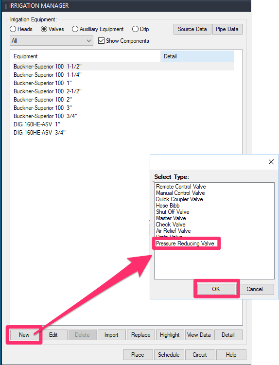
When you place an Irrigation Schedule, the pressure required downstream will be inserted into the schedule for the PRV. The entry in the schedule should match the setting of the valve.
If you want to show the pressure that the contractor needs to set for the regulator, you'll need to make these adjustments manually to the Critical Analysis and also to the schedule by adding an additional note in the description.
Shut-Off Valves (aka Isolation Valves)
Shut-off valves, also known as isolation valves, are able to close flow to – or isolate – loops of heads.
Shut-off valves figure prominently in golf course design, where they allow groundskeepers to eliminate flow temporarily to specific greens, fairways, etc., in order to complete maintenance. See our Golf Course Irrigation documentation for more information.
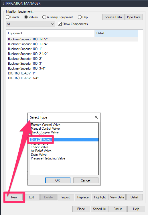
Shut-off valves are available as an option from the Valves menu in the Irrigation Manager.
If you plan to isolate a group of heads, or flow zone, using shut-off valves, keep in mind that it will require two shut-off valves. For example, you would need a shut-off valve at each end of a loop of rotors covering a fairway, as pictured below.

You would then pipe to those heads using a contiguous loop, will allow it to be closed off in both directions. This will prevent water from doubling back on itself in that loop and causing a rupture when the valves are closed.
Opening and Closing Shut-Off Valves
You can set a shut-off valve to be open or closed.
Setting a shut-off valve to closed blocks all flow downstream of that valve. When you verify your connections using our Highlight Station tool, it won’t highlight those areas. When you size the mainline, it won’t size in those areas.
For golf course design, we recommend setting shut-off valves to Closed in all flow zones but one (such as a fairway or green) before sizing the mainline. You can then size the mainline one zone at a time – opening the valves in areas to size while closing the rest – and working your way throughout the course in this way.
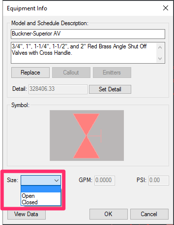
To select and edit a shut-off valve you've already placed, use our View Data/Edit Equipment tool. With this tool selected, you can then click each shut-off valve to open the Equipment Info dialog box (pictured above). There, you can set the valve to be open or closed.
Drip Control Valves (aka) Drip Kit Valves
Drip control, or drip kit, valves, are listed as drip equipment in our system. For instructions for adding these valves, see our adding drip equipment documentation.
Editing Valves
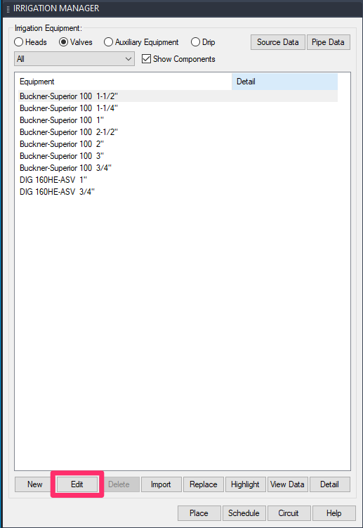
Once you've added a valve, you can view and edit its data and symbol by highlighting the valve in the Irrigation Manager and clicking Edit.
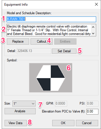
1. The top field contains the Model name. You're limited to only one line of text here.
2. This text box contains the Schedule Description. The text here is intended as a description of this valve, along with any other helpful information. The text in this box is limited to 256 characters.
3. Click Replace to replace the selected model with another equipment model.
4. Click Callout to select a new callout style for this valve. More information
5. If you want a detail associated with this item, click Set Detail.
6. This box contains a thumbnail image of the symbol assigned to this valve. Click the thumbnail image to see more details on the symbol or edit the symbol.
7. Depending on the valve, you might see several menus and fields in this area. Examples include a Size menu, where you can select a size for the valve, as well as text fields for flow (GPM) and pressure (PSI), an Analysis button to conduct a station analysis for the valve, and a text field where you can enter the elevation change from your site's water source to this valve.
8. Click View Data to see the manufacturer's performance data for this valve.
Importing Valves from a Template or Project
If you find yourself adding the same irrigation equipment to multiple projects, we recommend setting up a project template and then adding your commonly used valves to that template. You can then import individual valves into a new project from that template. This practice can save you immeasurable amounts of time, considering all the data you need to fill out for each valve you add. With templates, you only need to add and configure your valves once, then import it – along with all attached data – into the present project.
For instructions on importing valves and other irrigation equipment into a project, see our Importing Irrigation Equipment documentation page.
Take care when importing irrigation equipment from other projects. Remember that a manufacturer could have changed or even discontinued a product line or model since you last used it in a project.
Placing Valves in a Drawing
Placing Valves from the Irrigation Manager
To place a valve in your drawing, highlight it in the Irrigation Manager and click Place.
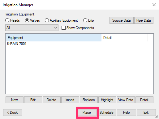
Click to place the valve. Depending on the valve, the Command line may prompt you to select a Rotation. Move your mouse to set a rotation for the valve, then click to set the rotation.
You can continue to place additional valves as necessary.
Placing Valves Using Our Place Valve Tool
You can also place valves in your drawing directly from the F/X Irrigation ribbon using our Place Valve tool.
Open the Place Valve tool:
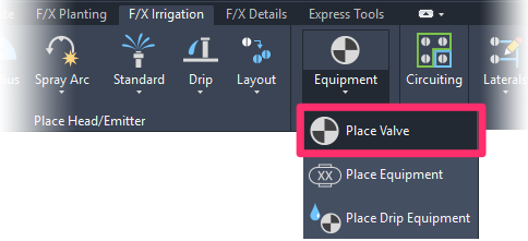
F/X Irrigation ribbon, Place Valve flyout
or type FX_PlaceValve in the Command line
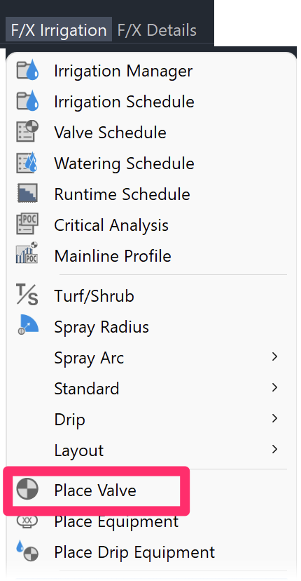
F/X Irrigation menu, Place Valve option
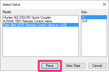
The Select Valve dialog box will open. Select a valve you've added to your project.
Select a Size for the valve, and click Place to place the valve in your drawing.
Renumbering Valves
You may find yourself modifying an irrigation plan that has already been sized and labeled. At times, this process may include combining zones, which will require you to delete one or more valves.
In this case, you'll notice that the Valve Schedule will skip the valve number(s) you've removed. Rather than deleting the old valves and re-creating them to correct the numbering, you can renumber the valves using the Valve Callout tool. For more information, see our Valve Callouts documentation.
To renumber valves, simply start with the lowest numbered valve. So, if for instance, you removed valve 5, you would click Valve Callout, and select valve 6, then change its number to 5, and the system will ask whether you wish to renumber the remaining valves.
Changing the Symbols for Valves in Your Projects and Drawings
If you've already added a particular valve to your project – even if you've already placed that valve in a drawing – you may want to change its symbol to another one of our default symbols, or a version you've created. See our documentation on changing valve symbols.
Information on Valves
For general information on valves, see the Valves article in our Irrigation Equipment documentation.
Changing the Symbols for Valves in Your Projects and Drawings
If you've already added a particular valve to your project – even if you've already placed it in a drawing – you may want to change its symbol to another one of our default symbols, or a version you've created. See our documentation on changing symbols for valves.
Related Webinars
- Irrigation for Beginners: We'll show how to navigate through the Irrigation ribbon and build a familiarity with our conceptual-level tools. You'll also learn the basics of adding equipment to a project, placing, piping, sizing, and scheduling. (1 hr 45 min)
- Getting Started with Irrigation F/X: This tour and tutorial will help you make the most of everything Irrigation F/X has to offer. We start with the fundamentals, such as how to set up your projects and Preferences, before diving into our collection of time-saving irrigation design tools. (59 min) Irrigation Tools – What You Need to Know: We'll show you the ins and outs of basic irrigation setup using our software, including how to add drip, sprays, and rotors to a project. (1 hr 6 min)
- How The Manufacturer Connection Works: The Manufacturer Connection is the relationship between the designer and manufacturer that Land F/X has used to separate ourselves from other design software programs. Learn how it helps you spec equipment for irrigation designs. (53 min)
- Irrigation Tips & Tricks: We'll show you some advanced tools you may or may not know about. You'll also learn techniques and best practices that will help speed up your workflow. (1 hr 3 min)
- Existing Irrigation: Learn the techniques, tools, and tricks you'll need to expand an existing system, including how to use a pipe cap to account for existing flow and add new valves to an existing mainline. (56 min)
- Advanced Irrigation Troubleshooting: Learn to think like a Land F/X irrigation troubleshooter. We'll show you why your symbols don't match, why you would see the message "Error accessing equipment data" (and how to fix these issues, as well as tips on pressure losses and precip rates, pipe caps, system monitors, and flow zones. (1 hr 3 min)
- Integrating Master Valves Into Your Design: With a focus on master valves, Dick Greenland from Buckner-Superior discusses how valves work, what pressure loss and flow considerations you need to keep in mind, and how to select a valve for a variety of design needs. (31 min)
- Golf Course Irrigation: We'll demonstrate some of the great tools Irrigation F/X offers to help ensure proper mainline sizing and scheduling. We'll also discuss the use of using flow zones, shut-off valves, and valve-in-head rotors. (1 hr 4 min)
Troubleshooting
Issue: A valve in your drawing has either no precipitation rate or too high of a precipitation rate
Issue: You want to create a dummy valve and assign it a flow (GPM)
Issue: CAD is crashing when you try to access a manufacturer's equipment
Issue: Error accessing equipment data in the project
Issue: Specify (add) equipment that is not currently in the database
Issue: Valves in separate areas are connecting or sizing automatically
Issue: You need to rescale valves in your drawing to accommodate a new drawing scale
Issue: You need to run multiple (two or more) valves at a time
Issue: Bad DXF group (10) error when placing irrigation equipment
Issue: The pressure loss is too high in your drip control valve or drip kit valve
Issue: Symbols for the same valve model have different scales or sizes in your drawing
Issue: High flow (GPM) calculated in your drip valves
Issue: You want to align or rotate valve symbols to the orientation of the mainline pipe
Issue: You saw a Missing File Error when attempting to place a valve
Issue: Error: File ... .dwg Was Created by an Incompatible Version of AutoCAD when placing valves
Issue: Error: "Unhandled exception in dcl-slideview-load ARX" when placing valves
Issue: You want to use Imperial valve sizes, but your drawing is set to metric units
Issue: The Irrigation Schedule is showing the incorrect quantitiy of remote control valves (RCVs)


