Working With External References (Xrefs)
Quick video
- Xrefs Overview
- Important! Before Attaching an Xref: Make Sure the Units are Set Correctly
- Equally Important! Clean Your Xrefs Before Attaching Them
- Attaching an Xref
- Path Type
- Overlay vs. Attachment
- The Specify on-Screen Setting
- Fading an Xref (Adding Transparency)
- Using Xrefs in Details
- Detaching an Xref
- Work Areas in Xrefs
- Xrefs and Schedules: Calculating Objects in Xrefs
- Configuring the Xref Manager
- Problems With the Xref Manager? Try the Classic Version
- Labeling Objects in Your Xrefs from Your Main Drawing
- Relevant Webinars
- Troubleshooting
Quick video
"External Reference" ("Xref") is just fancy AutoCAD-speak for a document you attach to a drawing. When you Xref a file into your drawing, you are doing the digital equivalent of what drafters did decades ago: laying a piece of tracing paper (your drawing) over an existing site base, planting plan, or any other document you would need as a basis for your site plan.
Xrefs Overview
Our fxREF tool simplifies the process of attaching Xrefs to a drawing. Just keep in mind that fxREF only works on DWG files. For more information, see our fxREF documentation.
You can Xref several document formats into a CAD drawing. Perhaps the most common format to Xref is another DWG file. (As you likely know, DWG is the file format of CAD drawings.)
To begin working with Xrefs, type Xref in the Command line and press Enter to open the Xref Manager (pictured to the right).

Important! Before Attaching an Xref: Make Sure the Units are Set Correctly
For an Xref to place and scale correctly with your main drawing, the Xref's Units setting needs to match the units and system of measurement (e.g., Architectural Inches, Decimal Feet, etc.) in which the Xref was originally drawn.
To verify the units setting, open the Xref. Type Units in the Command line, and press Enter.
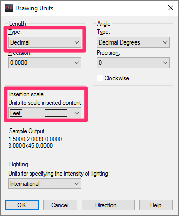
In the Drawing Units dialog box, make sure the unit Type and Insertion Scale settings match the units and measurement system in which that file was drawn.
For example, if it was drawn in Imperial units in Decimal Feet, the Type menu should be set to Decimal, and the Insertion Scale menu should be set to Feet.
Not sure of the units in which the Xref was originally drawn? Follow our instructions to Verify the Units.
The Unitless Setting (Options Dialog Box)
We highly recommend that you set both Insertion Scale menus to Unspecified - Unitless in the User Preferences tab of the Options dialog box.
(Open the Options dialog box by typing Options in the Command line and pressing Enter.)
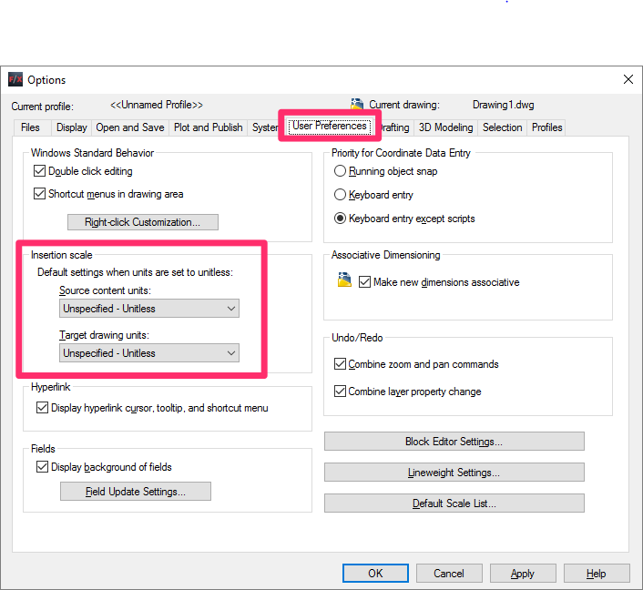
This option will prevent scaling issues should you need to Xref a drawing that was produced with the units set to Unitless.
Please see our CAD Options settings documentation page for more of our recommendations for configuring the CAD Options dialog box.
Equally Important! Clean Your Xrefs Before Attaching Them
Drawing corruption is a horrible reality of working with CAD files. Like a virus, corruption can result in slow performance and even the loss of work. Attaching Xrefs is a very effective way to infect your drawing with corruption.
For instance, Xrefs can transport hundreds or even thousands of Proxy Objects – a notorious cause of drawing corruption – into your drawing files.

To prevent drawing corruption, take care to clean each Xref before attaching it. We offer two methods for cleaning your Xrefs:
- Our Nuke tool
- Our manual drawing cleanup method (preserves layout tabs and User Coordinate Systems)
See our article on preventing drawing corruption for further information on keeping all your drawings clean.
Attaching an Xref

Don't see a DWG button? Your Xref Manager might have another file format enabled.
Click the small triangle in the top left corner of the Manager, and select Attach DWG from the menu that opens.


In the Select Reference File dialog box, navigate to the DWG you want to attach.
Click Open to attach the DWG you selected.
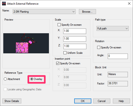
The Attach External Reference dialog box will open.
Click OK to attach the DWG file.
We recommend selecting the Overlay option under Reference Type when Xrefing a file. This will prevent several potential problems with your drawing file. For more information, see Why Should You Bring In Xrefs as Overlays? below.


The file will be Xrefed into your drawing.
You should now see an entry for it in the Xref Manager.
Xrefs, UCS, and WCS
If you have a User Coordinate System (UCS) active, any Xref you attach will use that UCS as the origin (0,0) for its insertion point and won't recognize the World Y axis. As a result, the Xref will come in skewed.
Before attaching one or more Xrefs, follow our steps to restore the World Coordinate System (WCS). You can then restore your UCS once you've attached all necessary Xrefs.
Path Types
When you attach an Xref, you can assign it one of three path types: Absolute, Relative, or No Path. Your image may not be appearing in your drawing because its path type, or its location, has changed. The Xref Manager allows you to click on an Xref and repath it as needed.
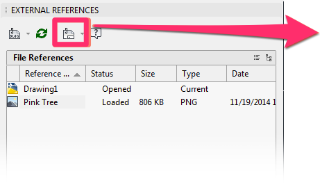
To repath an Xref, highlight it in the Xref Manager and click the Change Path button, which resembles a folder with a paperclip.
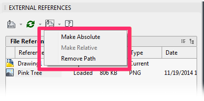
You can then select a path option from the menu that opens. In our example, the Xref currently has a Relative path, so we have the option to change it to an Absolute path or to Remove the path.
You have the following options for setting a path:
- Relative path: Images should be in a subfolder within the project folder
- Full path: The absolute path to the image – the entire filename, beginning with the drive that contains the image
- No path: The name of the image file (the image must be in the same folder as the current DWG drawing file)
Although we generally recommend using a relative path, the path type is up to you and what works best with your office. Here's a discussion of absolute vs. relative paths.
Overlay vs. Attachment
We recommend attaching each Xref as an Overlay rather than an Attachment most of the time, including when you cross-reference two drawings into each other.
While an Attachment Xref can be beneficial in some cases, most of the time it can cause complications.
Overlays and Attachments: A Comparison
Overlay:
- Doesn’t auto-attach nested Xrefs
- Usually better – prevents circular references
- Easier to maintain changes
- Allows one level of nests when used with attached nests
Attachment:
- Does auto-attach nested Xrefs
- Usually confusing – harder for newer users to understand nests and change paths
- Consultants like to send drawings Xrefed this way – sometimes the nests conflict
- Sounds faster to use, but ends up causing conflicts
- Works OK for single file trees
When Should You Bring In Xrefs as Overlays?
You should use an Overlay Xref when:
- You don't need to see nested Xrefs, or
- You plan on attaching nested Xrefs separately
An Overlay Xref is visible beneath the main drawing. The drawing can "read" objects in the Xref (such as plants), but the Xref does not become part of the drawing itself. Xrefing is a crucial tool in your drafting workflow.
To understand how Overlays and Attachments affect an Xref, we offer the following example.
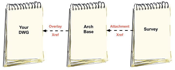
Let's say you receive an architectural plan that includes a survey base Xrefed into it. You then Xref the architectural drawing into your landscape plan.
If all Xrefs are embedded as Overlays, you will not see the survey in your landscape drawing. This is because if all drawings are Overlays, only the first Xref is brought in, and no nested Xrefs will follow.
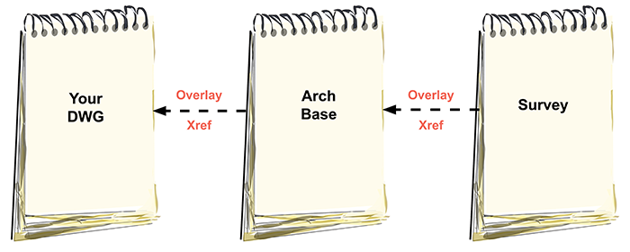
You can also use this method when:
- Xrefing two of your own drawings into each other, or
- Cross-referencing to prevent what's known as a circular reference – a drawing that references itself.
A drawing containing a circular reference will attempt to look at itself each time you upload references, effectively creating a problematic perpetual loop. To avoid this issue, always attach cross-referenced drawings as overlays.
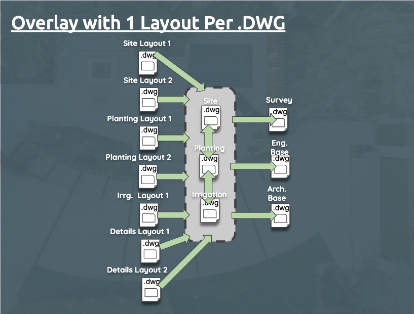
The diagram to the left shows a drawing with separate plans properly Xrefed as Overlays, with one layout per DWG that's brought in as an Xref.
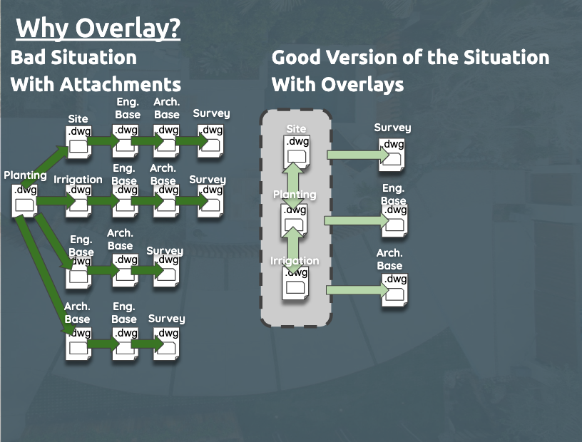
Here's another diagram showing a potentially bad situation that can arise when Xrefs are brought in as Attachments (left) and a better solution for bringing these same layouts in as Overlays (right).
Why You Should (Generally) Not Bring In Xrefs as Attachments
When you bring in an Xref as an Attachment, that Xref becomes part of the main drawing. If you have Xrefs within an Xref, they become "nested" in the main drawing. When carried out correctly, with a proper understanding of how Attachments and Overlays will interact, this practice can be beneficial.
In the following example, the Survey drawing is Xrefed into the Arch Base plan as an attachment, and the Arch Base plan is also Xrefed into the main drawing as an attachment. As a result, the Survey drawing will attach to the main drawing through nesting.
Furthermore, if the survey had an Attachment as well, that drawing would also be visible in your drawing. Though sometimes useful, this setup can often clutter the Xref list in your drawing with nested drawings that you don't need.

In this second example, the Survey drawing is Xrefed into the Arch Base plan as an attachment, but the Arch Base plan is Xrefed into the main drawing as an overlay. In this case, the Survey drawing will still attach to the main drawing through nesting. This occurs because overlaying still brings in one more level of nested Xrefs if the nested Xref is itself attached rather than overlaid. However, it would not bring in any further nesting.
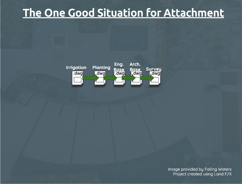
The diagram to the left shows the sole situation where you might consider Xrefs in as Attachments.
In this scenario, the planting plan is Xrefed into the irrigation plan, which is in turn Xrefed into the engineering base, and so on.
Using Attachments and Overlays strategically can keep your working document uncluttered. If in doubt, just bring in each Xref as an Overlay and include any nested Xrefs in your main drawing – also as Overlays.
The Specify on-Screen Setting
The Attach External Reference dialog box includes an option to Specify on-screen. Our recommendation for this setting depends on whether the Xref is already scaled.
Previously Scaled Xref/DWG
If you need to bring in a DWG, or an image (such as a site plan) that already has a scale, you'll need to:
- Leave the Specify on-screen option unchecked, and
- Enter a scale factor for the Xref
The example to the right shows the proper setting for Xrefing a DWG or image file with an existing scale of 1 inch = 30 feet into a drawing whose scale is set in Decimal Feet.
To account for this scale, we've unchecked the Specify on-screen option and entered a scale factor of 30.
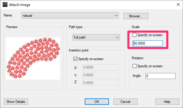
The scale factor you enter will depend entirely on the existing scale of the Xref and the scale of the drawing that is receiving the Xref.
Unscaled Image
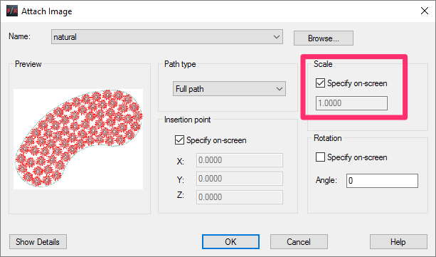
If you're Xrefing in an image that has no existing scale, we recommend checking the Specify on-screen option.
In this case, the scale factor is irrelevant – in fact, the field will be grayed out.
Once you've brought in the image as an Xref, you can scale it manually to match your drawing.
Fading an Xref (Adding Transparency)
You may want your Xrefs to be somewhat faded in your drawing (display fade) and/or when plotted (transparency), allowing your site design to stand out from the Xrefs behind it.
You can add a fade to your Xrefs using the Layer Properties Manager. You have two options in controlling the fade of the layers:
- Option 1: As an overall adjustment, no matter which viewport you are in
- Option 2: Viewport Override (VP Override). This option will allow you to pick the transparency per layout, giving you much deeper customizing abilities.
Option 1: Overall Adjustment of Transparency
1. Type Layer in the Command line and press Enter to open the Layer Properties Manager.
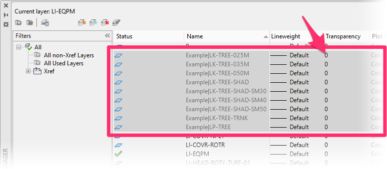
2. Filter the layers by Name, which will group all the Xref letters together.
Locate and highlight all the Xref layers. You can highlight multiple layers at once by holding down the Shift key while clicking. In this example, we'll select all the layers in an Xref named Example.
Scroll over to the Transparency column, and click to edit any one of the highlighted layers.
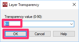
3. In the Layer Transparency dialog box, enter a new transparency value for your Xref layers between 0 and 90 (example: 60).
Click OK.
4. The transparency of all selected layers – that is, all layers in your Xref – will change to the new value.
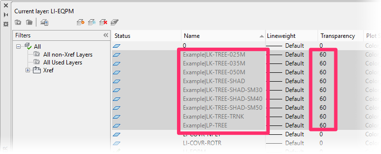
5. Run a plot preview, and check the results. Repeat the steps above until your Xref has your desired level of transparency.
Option 2: Choose the Transparency Per Layout
Keep in mind that the method described below will only only affect the Viewport in which you perform the steps. You can repeat these steps for each additional viewport where you want to fade an Xref.
1. Type Layer in the Command line and press Enter to open the Layer Properties Manager.
2. Filter the layers by Name, which will group all the Xref letters together.
Locate and highlight all the Xref layers. You can highlight multiple layers at once by holding down the Shift key while clicking. In this example, we'll select all the layers in an Xref named Example.
Scroll over to the VP Transparency column, and click to edit any one of the highlighted layers.
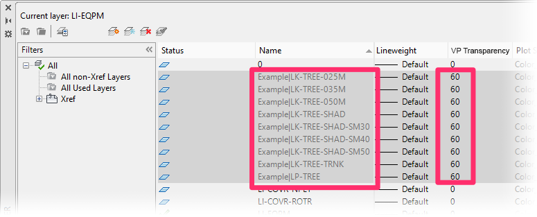

3. In the Layer Transparency dialog box, enter a new transparency value for your Xref layers for the selected viewport between 0 and 90 (example: 60).
Click OK.
4. The transparency of all selected layers – that is, all layers in your Xref – will change to the new value for the selected viewport.

5. Run a plot preview, and check the results. Repeat the steps above until your Xref has your desired level of transparency in the viewport you selected.
Using Xrefs in Details
Quick video
For tips on using Xrefs in details, see our Using Xrefs in Details Power Tip, linked to the right.
Detaching an Xref
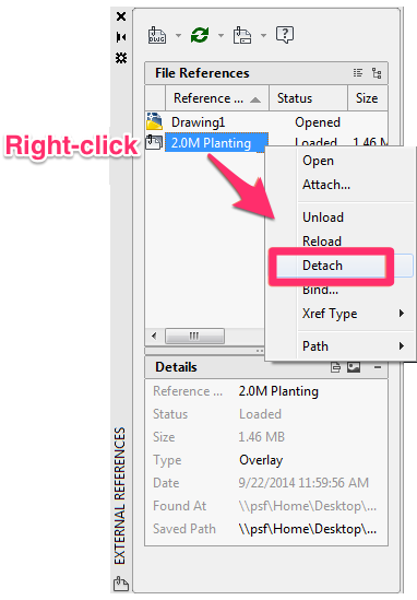
To detach an Xref, right-click it in the Xref Manager.
Then select Detach from the menu that opens.
If an Xref doesn't detach, it might be locked, nested within another Xref within the drawing. In this case, you may need to do some manual deletion and investigation – or change your Overlay/Attachment options.
Work Areas in Xrefs
Our software now recognizes Work Areas in your Xrefs. A Work Area, like a drawing within a drawing, allows you to divide your site design into distinct regions. This in turn allows you to:
Set different scales throughout your drawing
- Limit your schedules (such as Plant, Irrigation, and Reference Notes schedules) to specific areas or project phases
- Simplify error checking
For more information, visit our documentation pages on:
Xrefs and Schedules: Calculating Objects in Xrefs
Our Plant Schedule and Reference Notes (RefNotes) Schedule tools both offer options to Include Xrefs in the schedule. When you select this option, the schedule will calculate and list any pertinent objects that have been placed in one of the Xrefs.

Option to Include Xrefs, Plant Schedule dialog box

Option to Include Xrefs, Reference Note Schedule dialog box
Keep in mind that this feature will only recognize plants or Xrefs that have been placed in drawing files that have been directly Xrefed into the main drawing. It won't recognize objects that are in an Xref within an Xref (known as a "nested Xref"). If you notice that your schedule is not counting some of the objects within your Xrefs, the problematic objects are likely within a nested Xref. If so, please follow our instructions to correct this issue.
Configuring the Xref Manager
The Xref Manager includes a few options for how you view and preview your Xrefs. For detailed information, see our Configuring the Xref Manager documentation page.
Problems With the Xref Manager? Try the Classic Version
If the Xref Manager is giving you issues, you might want to try the classic Xref Manager.
To revert to the classic version (pictured to the right), type ClassicXref in the Command line and press Enter.

To return to the newer Xref Manager, type Xref in the Command line and press Enter.
Labeling Objects in Xrefs from Your Main Drawing
Want to label plants, Concept Plants, or Reference Notes (RefNotes) in your Xrefs from your main drawing without opening the Xref separately? Here's how:
Labeling Plants and Concept Plants
To label project plants or concept plants in your Xrefs, use any of our plant labeling tools in your Xrefs in conjunction with our Edit Reference In-Place tool.
Labeling Reference Notes (RefNotes) in Your Xrefs
You can easily call out RefNotes in your Xrefs while still working inside your main drawing, without having to use our Edit Reference In-Place tool. Just make sure that both the drawing you’re labeling inside and the Xref drawing are set to the same Land F/X project. Then label your RefNotes as you would normally.
Relevant Webinars
- Xref Tips and Tricks: Looking to improve your office drawing production workflow? This webinar takes a look at a scalable setup for drawings using external references (Xrefs), showing you how and why you should use them. We also go over our fxREF tool, as well as the other Land F/X tools that improve with the use of Xrefs. (1 hr 3 min)
- Drawing Setup: Using an Image: Pick up some recommendations and best practices for bringing an image into your base file, from setting up your file to choosing and scaling your image, tracing key elements, setting up your layers, and configuring a sheet and viewport for plotting. (1 hr)
- F/X CAD for New AutoCAD Users: Learn AutoCAD best practices to establish good habits, including the best practices for setting up a drawing with an Xref. (59 min)
Troubleshooting
Issue: You are unable to attach Xrefs, or Xrefs are detaching
Issue: Xrefs are missing when you open your drawing
Issue: Xrefs are not coming in at 0,0
Issue: The Plant Schedule is showing the incorrect groundcover quantity or area in a drawing with Xrefs
Issue: A Drip Area in your irrigation plan isn't reading the plants in an Xref
Issue: When you place irrigation symbols, they are coming in beneath the Schematic Irrigation Xref
Issue: Xref Manager is opening slowly the first time you attempt to open it after starting CAD
Issue: Your Xrefs are coming in skewed, twisted, or crooked
Issue: The Plant Schedule or Reference Notes Schedule is not recognizing or calculating objects in an Xref
Issue: Raster images, JPEGs, or logos are disappearing from your drawing when you plot
Issue: An Xref is not scaling to your drawing correctly
Issue: You are receiving an "INVALID" message in the Command line when trying to attach Xrefs
Issue: Layers from one or more of your Xrefs are not visible within a viewport or Work Area
Issue: Dimensions are being displaced, moving, or going off into space after you detach an Xref
Issue: Images and PDFs are appearing as "Unreferenced" in the Xref Manager
Issue: Your Xrefs disappear when you try to zoom or pan


