Placing Spray Heads
Quick video
- Placing Spray Heads: Overview
- Step 1: Open the Turf/Shrub Tool
- Step 2: Select a Model
- Step 3: Select a Radius
- Step 4: Select an Arc Pattern
- Keyboard Commands for Placing Heads
- Layout Tools for Placing Heads
- Editing or Viewing Information about Heads
- Replacing Heads
- General Information About Heads
- Changing the Symbols for Spray Heads in Your Projects and Drawings
- Related Webinars
- Troubleshooting
Once you've added a spray head type to a project, all nozzles and options for that model, and their related symbols, will be automatically available to place in your drawing, along with all performance data relating to the design pressure you've selected. You can easily select and place heads on the fly using the spray flyouts on the F/X Irrigation ribbon.
The default install does not include all symbols, but many of them will download on demand. If you go to place a head, the symbol should download as necessary. If you want, you can also have the system download all irrigation symbols from the Check for Updates feature.
Placing Spray Heads: Overview
The tools for placing a spray head are all available as flyouts and buttons in the Place Head/Emitter panel of the F/X Irrigation ribbon.
This method of placing heads is essentially a four-part process:
1. Open our Turf/Shrub tool from the F/X Irrigation ribbon.
2. You'll now see a dialog box displaying a list of spray head models you've added to your project. Select the model you want to place, then click OK.
You can also click Turf Spray - <Add New> or Shrub Spray - <Add New> to add a turf or shrub spray head model to your project as you would from the Irrigation Manager, then proceed with placing that model in your drawing.
3. Select the radius of the nozzle you want to place.
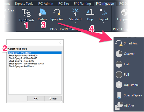
4. Select the arc or spray pattern of the nozzle you want to place.
The arc options are Smart Arc, Adjustable, or a fixed arc of Quarter, Half, or Full. If you're placing a special spray pattern, such as a strip spray, click Special Spray.
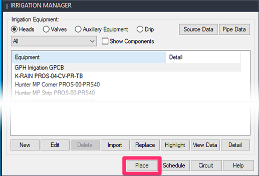
You can also place spray heads:
- From the Irrigation Manager (pictured to the left) by either:
- Highlighting the head and clicking Place, or
- Double-clicking the head
- Using a series of keyboard commands
Step 1: Open the Turf/Shrub Tool
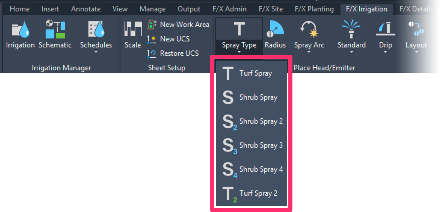
As of 2021, you no longer need to select a turf or shrub spray type from a flyout menu to place. Just open our Turf/Shrub tool from the F/X Irrigation ribbon (pictured below) or type FX_HeadType in the Command line.

If you still have the old ribbon or have typically used the flyouts from the F/X Irrigation pull-down menu, you can click any of the Spray Type flyout buttons to open the selection dialog box you'll see in the next step. Note that toolbars have been discontinued.
To get the latest ribbon, download and install our latest F/X Workstation installer.
Step 2: Select a Model
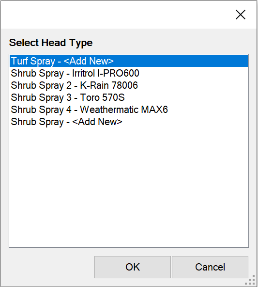
You'll now see a dialog box listing all spray head models that have been added to your project. If you want to place one of these models, select it from the list and click OK.
You can also choose to add a new spray head model to your project. Click Turf Spray - <Add New> to begin adding a new turf spray heas, or Shrub Spray - <Add New> to add a new shrub spray head to your project.
Step 3: Select a Radius
Next, select the Spray Radius tool to select the radius of the head you're placing:

F/X Irrigation ribbon, Radius button
Type FX_IrrigRadius in the Command line
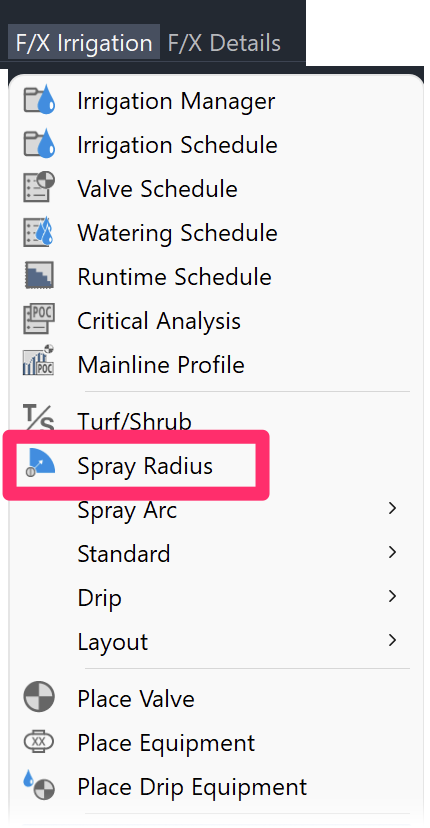
F/X Irrigation menu, Spray Radius option
The Select Radius dialog box will open. The options listed will be those that apply to the selected head.
Click your desired radius to select it.

Step 4: Select an Arc Pattern
Once you've selected a spray head type and radius, select an arc pattern for the head. You have a few options:
Adjustable Arc
To place an adjustable arc, select the Adjustable Arc tool:
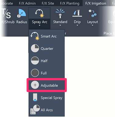
F/X Irrigation ribbon, Adjustable flyout
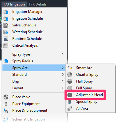
F/X Irrigation menu, Adjustable Head flyout
or type FX_PlaceADJ in the Command line
When you select this option, your cursor will turn into a "target," which reflects the radius selected and with a text indication of the radius and arc – in this case, 15V for a 15-foot variable (adjustable) arc.

Move the target to the location in the drawing where you want to place the head, then click to place a head in that location.
The Command line will prompt you to set a Spray arc start point.

Use the cursor to define the beginning and end of the arc pattern.
Remember to move the mouse counterclockwise.
When you click the second point, the head will be inserted and offset into the spray area. The arc pattern will be defined clearly where you started and ended the pattern. The target will remain, as you may wish to place additional adjustable arc heads. You can also end the function by pressing Esc or by right-clicking.
"Smart Arc"
Open the Smart Arc tool:
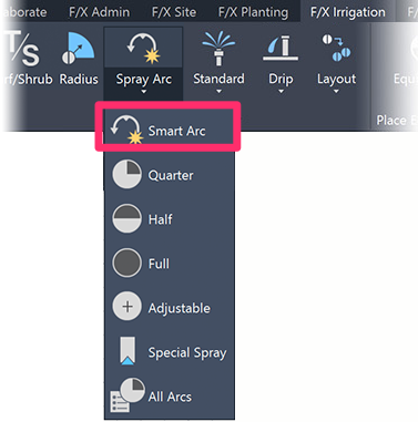
F/X Irrigation ribbon, Smart Arc flyout

F/X Irrigation menu, Smart Arc flyout
or type FX_PlaceSmart in the Command line
Selecting a Smart Arc will present a "target," which reflects the radius selected and with a text indication of the radius and arc – in this case, 15-* for a 15-foot Smart Arc.
Move the target to the location where you want to place the head. Click to place a head there.
Now define the beginning and end of the arc pattern. Remember to move counterclockwise.

The second point of the Smart Arc is the edge of the planted area. The arc itself will usually extend a little beyond this location, as shown below. When you click this location, the arc will “adjust” for equal overspray at the start and end of the planted area, and a symbol will be inserted to the arc – in this case, a quarter arc head.

Defining the second point of the arc

Clicking the second point, which inserts the symbol
Fixed Arc (Quarter, Half, or Full)
The F/X Irrigation ribbon includes buttons for the three most common fixed arc nozzles: Q (Quarter), H (Half), and F (Full). To select one of these options, click the appropriate button.
If you want a different arc, or are unsure of the arc you will need, use our Smart Arc tool to have the complete arc pattern available as you define the planted area.
To place a fixed arc, click one of the three fixed arc tools: Quarter, Half, or Full:
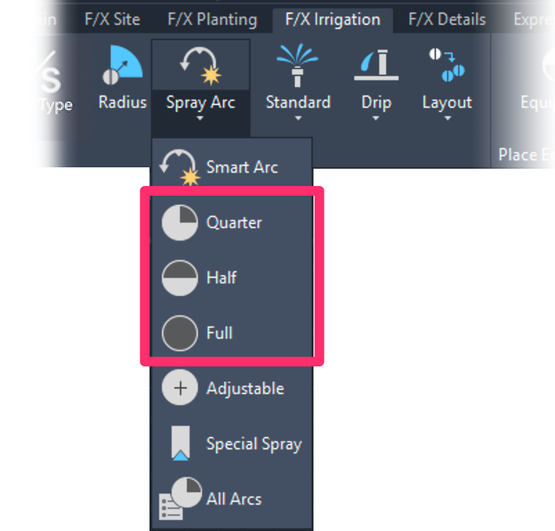
F/X Irrigation ribbon, Quarter, Half, and Full flyouts

F/X Irrigation menu, Quarter, Half, and Full flyouts
Keyboard Commands:
- FX_PlaceQ(Quarter)
- FX_PlaceH(Half)
- FX_PlaceF(Full)
In our example, we've selected the Quarter tool to create a quarter arc.
Because we've specified a 15-foot radius, a "target" containing the text 15Q has become active.

Move the target to the location where you want the head, and click to place it. Now move the orientation of the arc to the desired direction. When you click to set the orientation, a head symbol and the arc pattern will appear in the location you've selected.

The Quarter head is placed and the orientation adjusted.

Clicking to set the orientation will place the symbol and arc pattern.
Selecting a Special Spray
The Special Spray option allows you to place any turf or shrub spray model types you have added to your project. Click either Shrub Spray or Turf Spray (if both are indicated), then click the “Nozzle” type you are looking for. In this case, a Rain Bird model has been added, and all “Special Spray” nozzles are indicated, such as strip sprays, 8-foot flat spray, square sprays, etc.
Select the Special Spray tool:
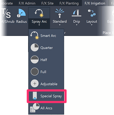
F/X Irrigation ribbon, Special Spray flyout

F/X Irrigation menu, Special Spray flyout
or type FX_PlaceStrip in the Command line
The Select Special Spray dialog box will open.

1. The Model pane lists all head models that have been added to the project. Select your desired model.
2. The Nozzle pane lists all available nozzles. Select your desired nozzle.
3. Click the Place to place the Special Spray in your drawing.
4. Click View Data to view data about the selected equipment on the manufacturer's website.
In our example, we'll place some strip sprays, with the target reading 15EST for a Rain Bird end strip spray.

Keyboard Commands for Placing Heads
We offer numerous handy keyboard commands for placing heads. For information and innstructions, see our Keboard Commands for Placing Heads documentation.
Layout Tools for Placing Heads
We also offer a series of Layout tools to help you lay out and place heads quickly throughout your drawing. See our documentation on the following tools:
- Rectangular and Triangular Grid tools
- Rectangular and Triangular Array tools
- Copy Along Polyline
- Copy Along Line
- Match Head
- Match Properties
Editing or Viewing Information about Heads
The Edit Head / View Data tool allows you to see the model, flow, and design pressure of any selected head. This feature can be helpful in familiarizing yourself with a plan, or in finding out the flow required by an adjustable spray head. It also allows you to edit the design pressure, description, or nozzle. For more information, please see our Edit Equipment / View Data documentation page.
Replacing Heads
The Replace tool, available in the Equipment Info dialog box, allows you to replace all instances of an existing head in your drawing with another model. For more information, see our Replace Equipment documentation.
Many users run the Replace tool unnecessarily. Note that you can edit the text and model of any piece of equipment directly, without the need to use Replace.
General Information about Heads
For general information about sprinkler heads, see the Sprinkler Heads portion of our Irrigation Equipment Definitions documentation.
Changing the Symbols for Spray Heads in Your Projects and Drawings
If you've already added a particular spray head to your project – even if you've already placed that head in a drawing – you may want to change its symbol to another one of our default symbols, or a version you've created. See our documentation on changing symbols for spray heads.
Related Webinars
- Getting Started with Irrigation F/X: This tour and tutorial will help you make the most of everything Irrigation F/X has to offer. We start with the fundamentals, such as how to set up your projects and Preferences, before diving into our collection of time-saving irrigation design tools. (59 min)
- Irrigation for Beginners: We'll show how to navigate through the Irrigation ribbon and build a familiarity with our conceptual-level tools. You'll also learn the basics of adding equipment to a project, placing, piping, sizing, and scheduling. (1 hr 45 min)
- Start to Finish Basics of Irrigation Design: This webinar will help give you an understanding of how to specify the proper equipment, talk about important concepts of irrigation design, and create a complete irrigation plan from start to finish. (1 hr 31 min)
Troubleshooting
Question: Is there a good way to show that a particular spray head is on a riser in an irrigation plan?
Issue: When I pipe to a head, the "snap" point is wrong
Issue: One of my heads is coming in oversized. All others seem to be fine.
Issue: Error accessing equipment data in the project
Issue: Wrong irrigation symbols coming in
Issue: When you place heads or other equipment, they are coming in at the wrong scale
Issue: You want to make the spray radius lines of your heads visible when you plot or plot preview
Issue: Heads in separate areas are connecting or sizing automatically
Issue: You need to rescale irrigation heads in your drawing to accommodate a new drawing scale
Issue: Heads' insertion points seem to be slightly offset from each other when placed
Issue: When placing a rotor, you are unable to see your desired nozzle size
Issue: Bad DXF group (10) error when placing irrigation equipment
Issue: Symbols for the model of head have different scales or sizes in your drawing
Issue: You changed the scale in your drawing, but new heads you place are not respecting the change
Issue: You are trying to switch from turf spray to shrub spray, but the symbols are not changing
Issue: You want to turn sprinkler arcs on once they are turned off
Issue: You have lateral pipe running through the middle of one or more of your spray heads
Issue: Your heads are placing with the incorrect symbol family
Issue: You saw a Missing File Error when attempting to place a head
Issue: Your spray head symbols are showing up with transparency when placed in your drawing


