Placing Standard Heads (Rotary, Rotor, Impact, Bubbler)
Quick video
- Place Standard Heads: Overview
- Placing Rotary Heads
- Placing Rotor Heads
- Placing Impact Heads
- Placing Bubbler Heads
- Keyboard Commands for Placing Heads
- Layout Tools for Placing Heads
- Editing or Viewing Information about Heads
- Replacing Heads
- General Information About Heads
- Changing the Symbols for Spray Heads in Your Projects and Drawings
- Related Webinars
- Troubleshooting
Once you've added a rotary, rotor, impact, or bubbler to a project, all nozzles and options for that model, and their related symbols, will be automatically available to place in your drawing, along with all performance data relating to the design pressure you've selected. You can easily select and place heads on the fly using the Standard flyouts on the F/X Irrigation ribbon.
The default install does not include all symbols, but many of them will download on demand. If you go to place a head, the symbol should download as necessary.
Place Standard Heads: Overview
The tools for placing rotaries, rotors, impact heads, and bubblers are available as:
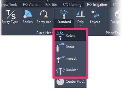
• Flyouts on the Standard flyout menu on the F/X Irrigation ribbon

• Flyouts from the Standard option on the F/X Irrigation menu
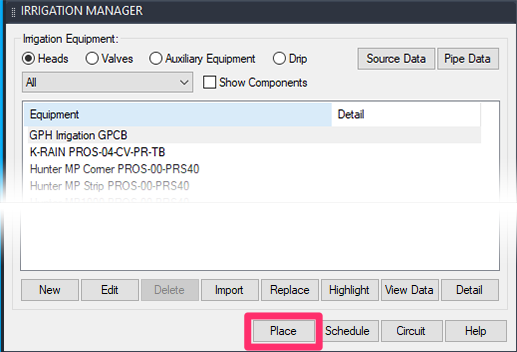
You can also place these heads:
- From the Irrigation Manager (pictured to the left) by either:
- Highlighting the head and clicking Place, or
- Double-clicking the head
- Using a series of keyboard commands
Placing Rotary Heads
Rotary Heads are known by several names (e.g., Rain Bird Rotary Stream, Hunter MP Rotator, Toro Precision Rotating).
Open the Rotary tool:
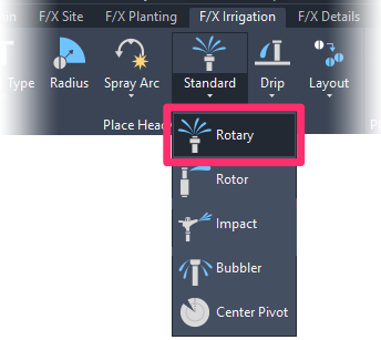
F/X Irrigation ribbon, Rotary flyout

F/X Irrigation menu, Rotary option
or type FX_PlaceRotary in the Command line
We updated our rotary symbol library in 2020, offering 8 families with 25 symbols per family. More information
The Select Rotary dialog box will open.
Here, you'll see a list of all rotary head types you've added to your project.
Click the Model and Nozzle type you want to place. Then click Place to place the rotary head.
You don't necessarily have to select one of the nozzles for the selected type. A nozzle will be assigned automatically based on the arc pattern.

.png)
You might see a number in parentheses (for example, (2), (3), (4), etc.) in the name of a rotary model as listed in the Irrigation Manager.
This number indicates the order in which the head was added to the Irrigation Manager if the project includes more than one of the same model type.
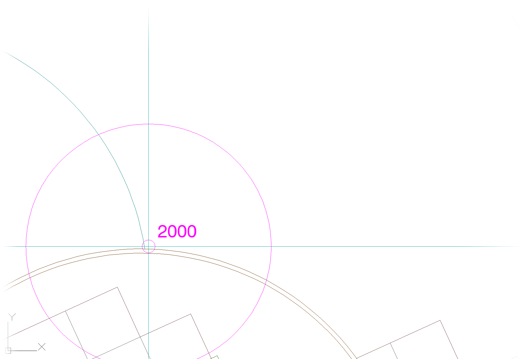
When you place a rotary head, a target will appear at that nozzle's diameter, with a designation for this head – in this case, 2000.
Move the target to the head location.
Click to place the head, then click two points to define the arc pattern.
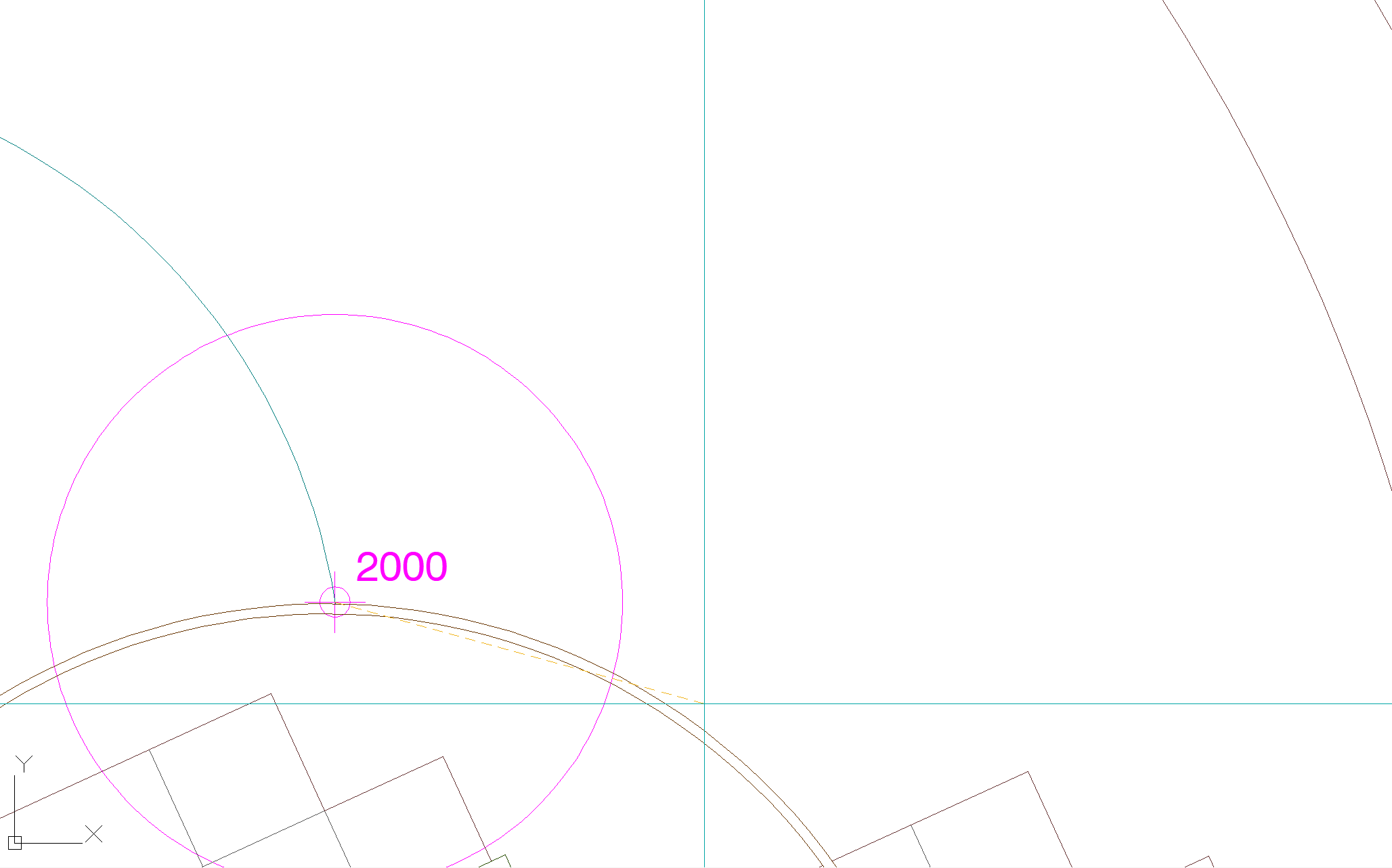
When you define the arc, you may notice limitations on what the arc can do. For instance, the arc pattern may be forced to start at 90 degrees and/or stop at 270 degrees because the specified nozzle does not go beyond those angles.
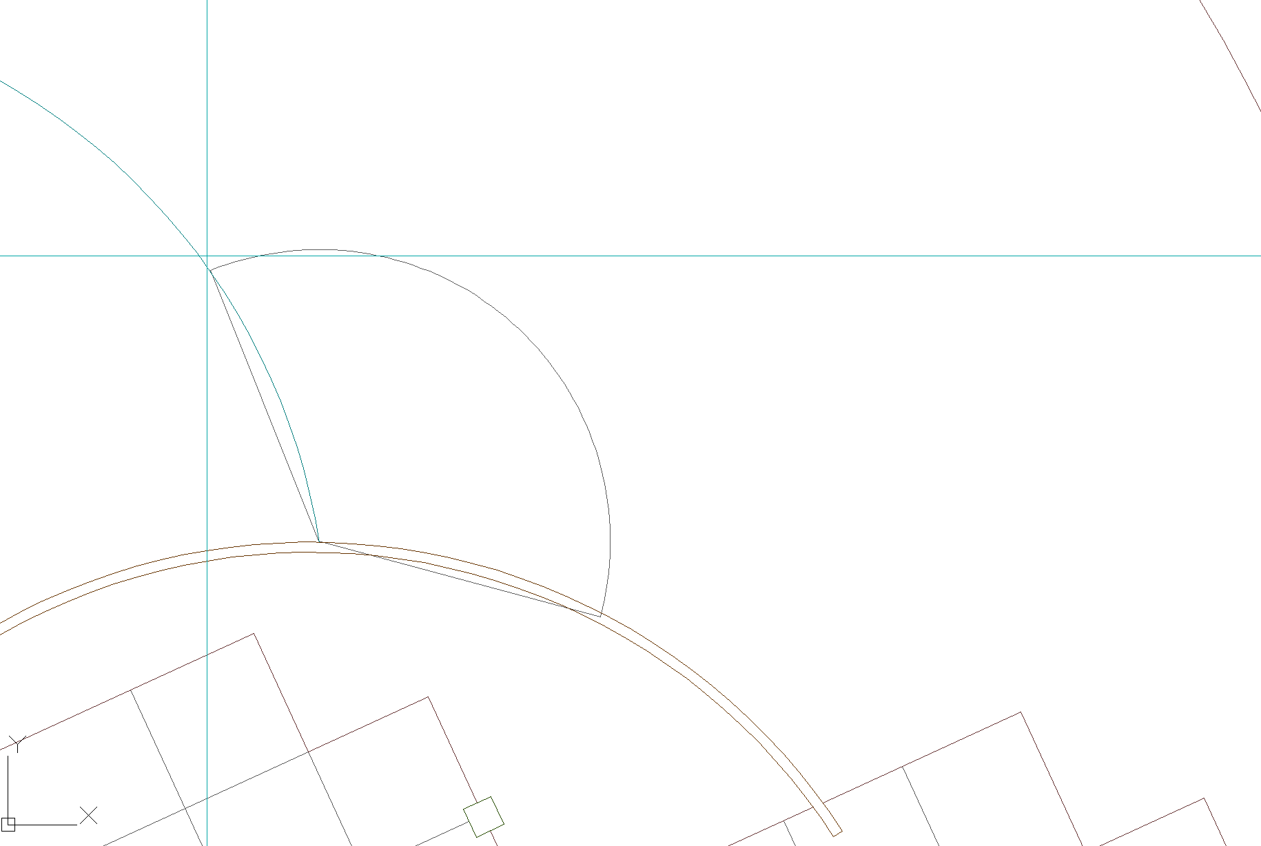
When you click to stop the arc definition, a head symbol, with the correct nozzle for the arc, will be placed and the selected arc pattern.
Note that we've updated our rotary symbols as of 2020. Rotary symbols now include an arc spray direction that will show up automatically when you place the symbol, pointing in the general pattern and direction of the placed head, as in the example shown here.
For more information, see our expanded rotary symbols library documentation.
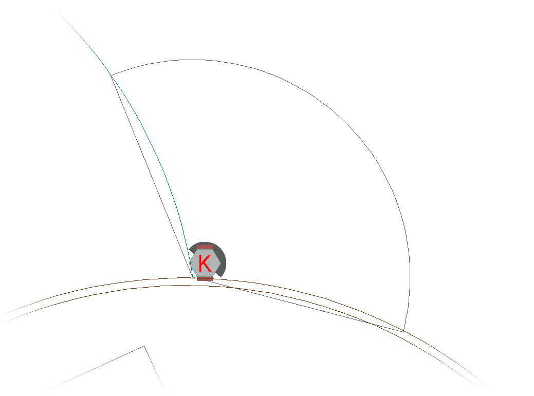
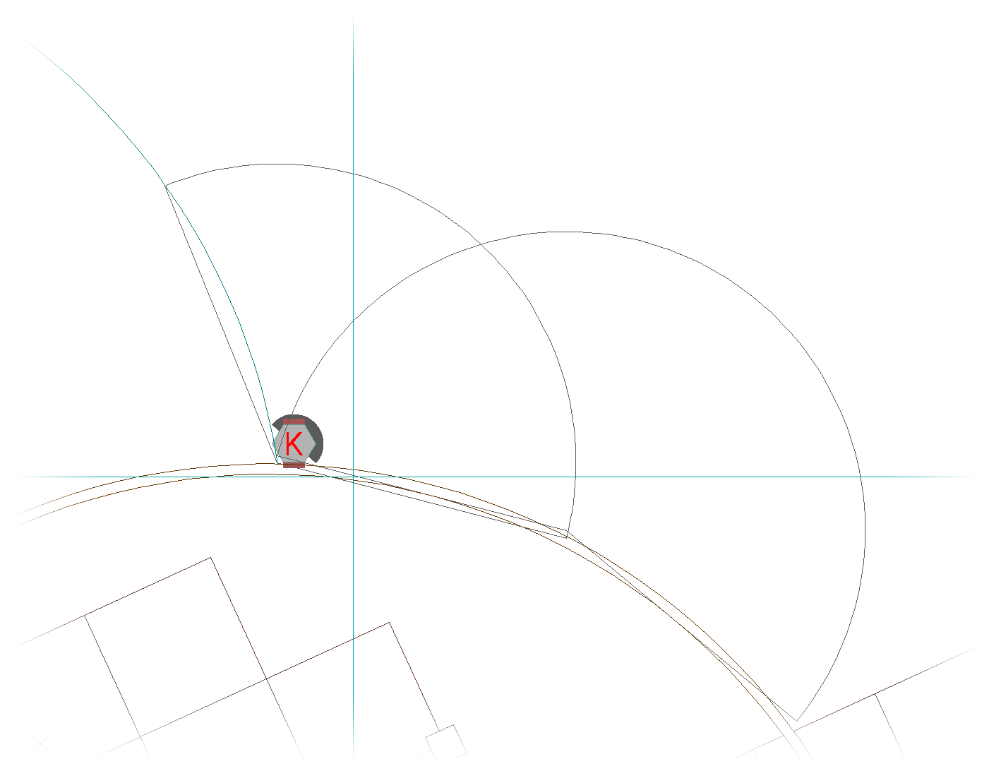
Placing another rotary head with a larger arc pattern
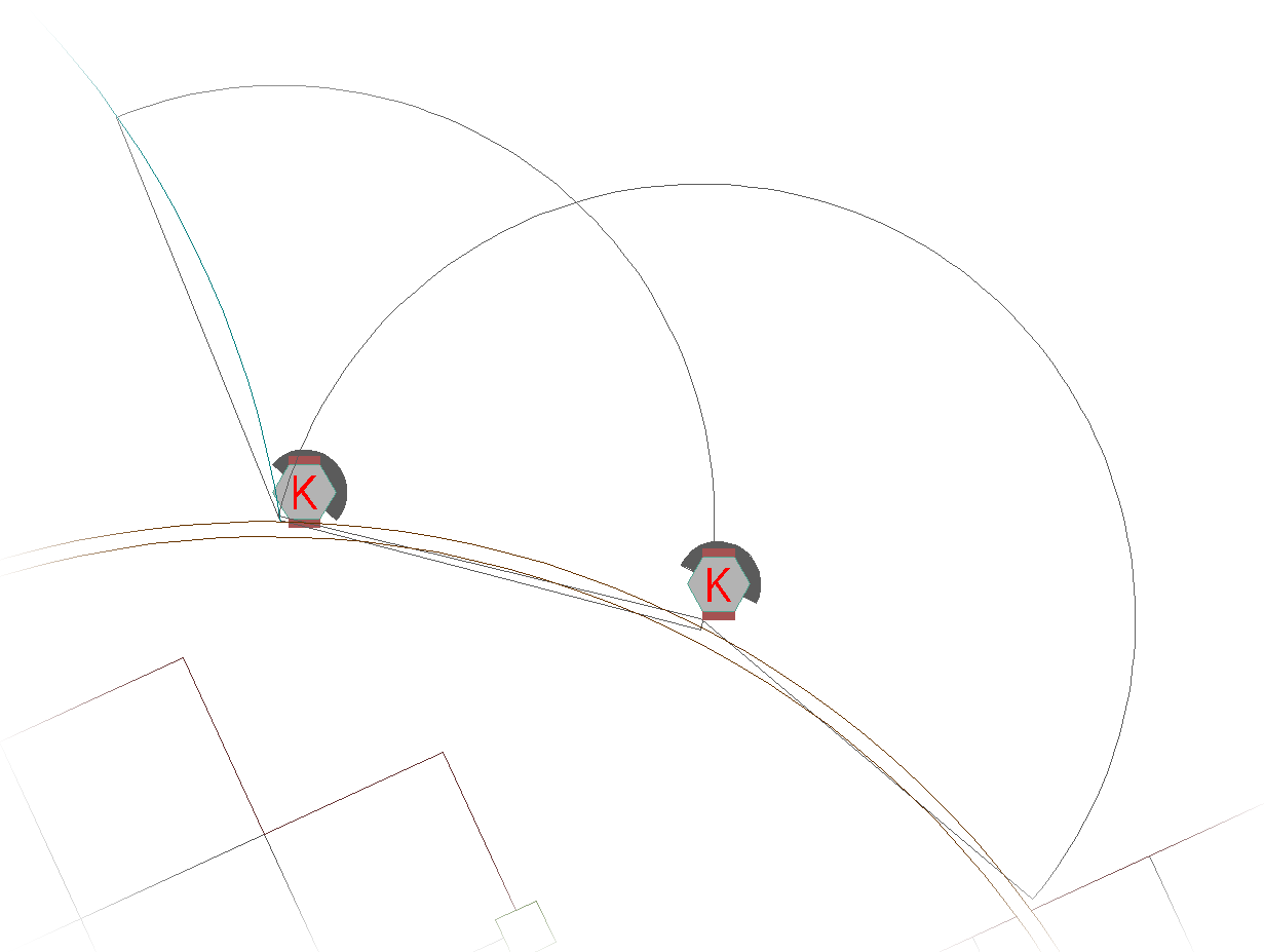
That rotary head symbol is placed
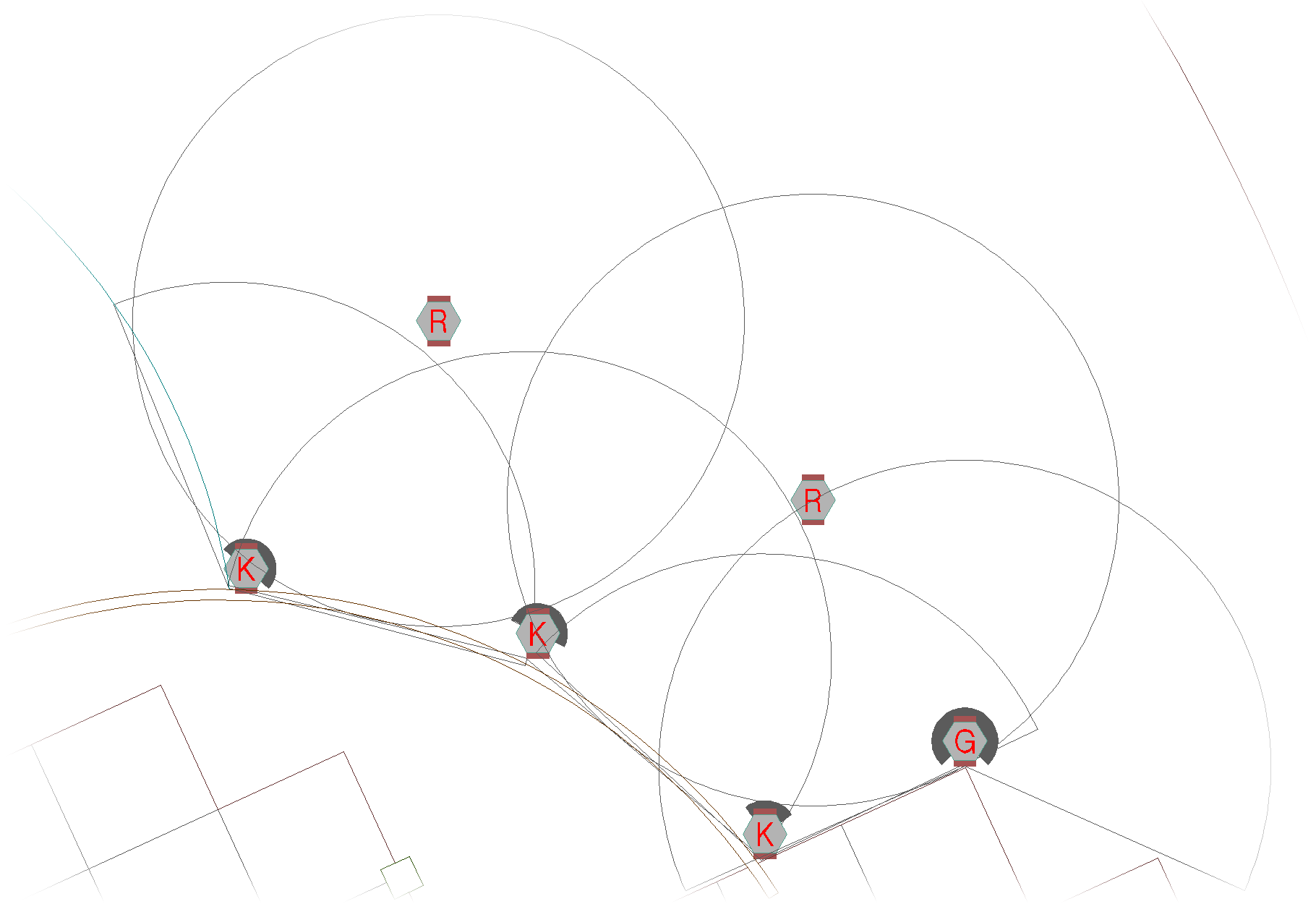
Notice the different nozzle designations in the two heads. These different designations occur because an arc between 90 and 210 degrees appears in black (K), and an arc between 210 and 270 degrees appears in green (G). The second head went beyond 210 degrees and was automatically designated G for "green."
The new arcs placed with each head follow the same logic as when it places a Q, H, TQ or Full (no arc).
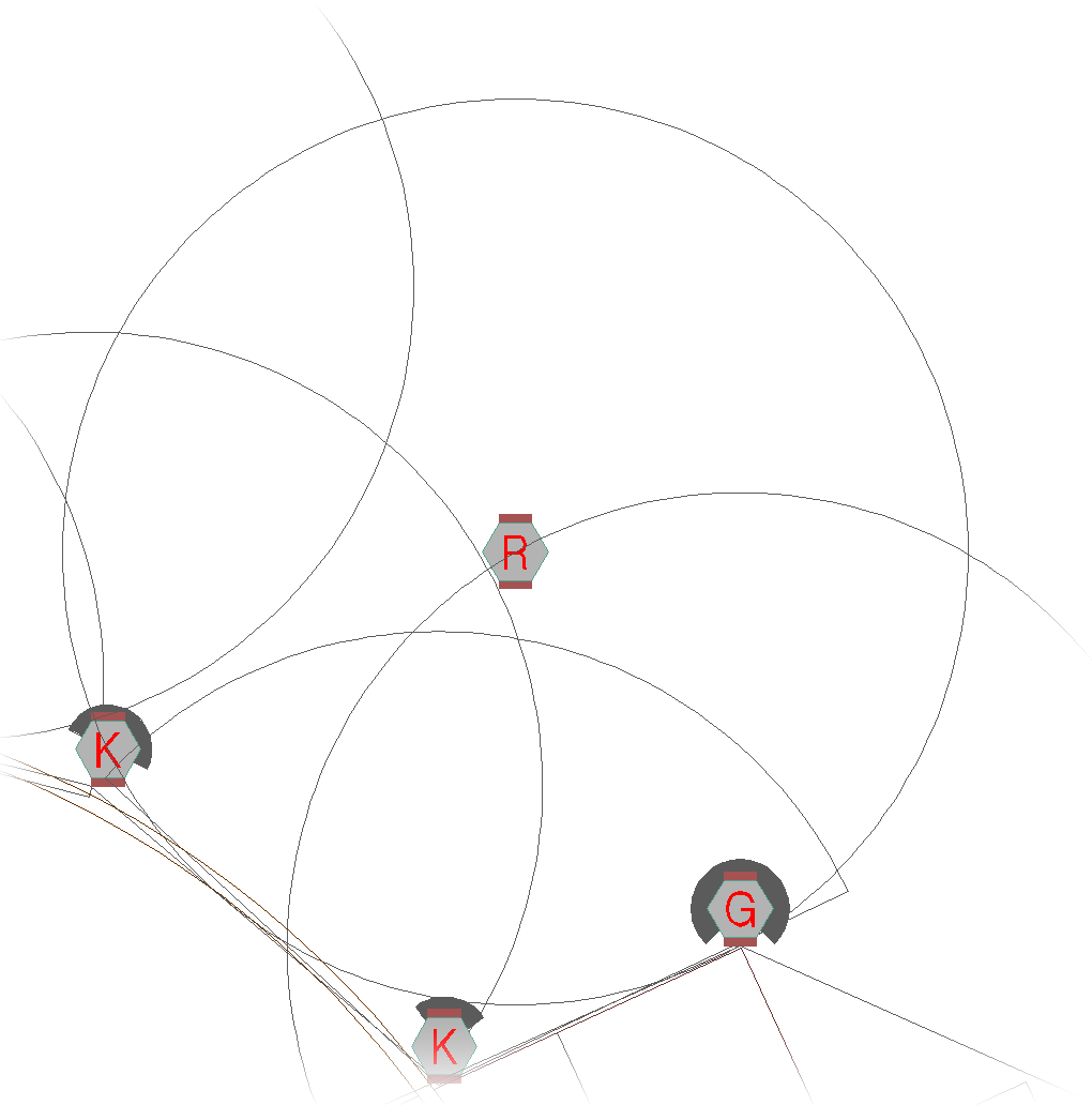
To place a full-circle rotary head, move the target to the proper location. Click to place the head, then right-click to insert a full-circle (360 degree) nozzle.
If you want a full-circle, 360-degree arc, do not try to define it by clicking two points. Simply right-click with the mouse, and a 360 degree arc will appear.
When you're placing rotary heads, the keyboard command tools are perhaps the most critical tools to use in order to jump quickly between different nozzle patterns when viewing the target for head placement. Using these tools, you can move from the 2000 to the 1000, and then back up to the 3000 very quickly, then see the results on the target.
Placing Rotor Heads
Quick video
When you add a rotor spray head manufacturer, series, and model to represent a rotor head type, all nozzles and options for that model become automatically available for input into the drawing.
The heads will also automatically indicate all performance data conforming to the manufacturer's specifications, and all symbols set up for placement.
Open the Rotor tool:
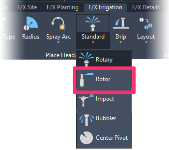
F/X Irrigation ribbon, Rotor flyout

F/X Irrigation menu, Rotor option
or type FX_PlaceRotor in the Command line
We now offer three different rotor symbol types: No Rotation, Arc Rotates, and Symbol Rotates. The Arc Rotates and Symbol Rotates symbol types have distinct ways of indicating the direction of the spray, while the No Rotation type does not show the spray direction. More information
The Select Rotor dialog box will open, listing all rotor models, shrubs, and turf you've added to the project. When you highlight a model, the available nozzles will display to the right.
Click Place to place the selected rotor.

Can't see your desired nozzle size? That size may not be available for the design pressure you selected for the rotor. More information
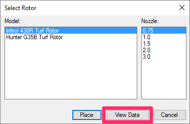
If you need more information, click the View Data button in the bottom left corner of the dialog box.
The performance data for the highlighted head will display through your Web browser.
Viewing the performance data is a helpful tool for making decisions on which nozzle is best suited for your requirements.
The rotor is ready to place. Click where you want to place it.
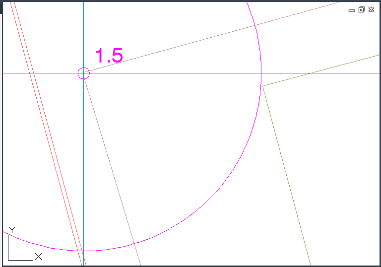
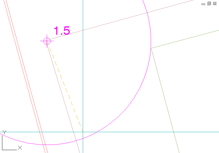
If you've selected an adjustable nozzle, click the start and end point of the pattern in a counterclockwise direction.
If you're placing a full-circle rotor, you won't attempt to define it with two points, as you would an adjustable arc.
Just right-click to place a full circle.
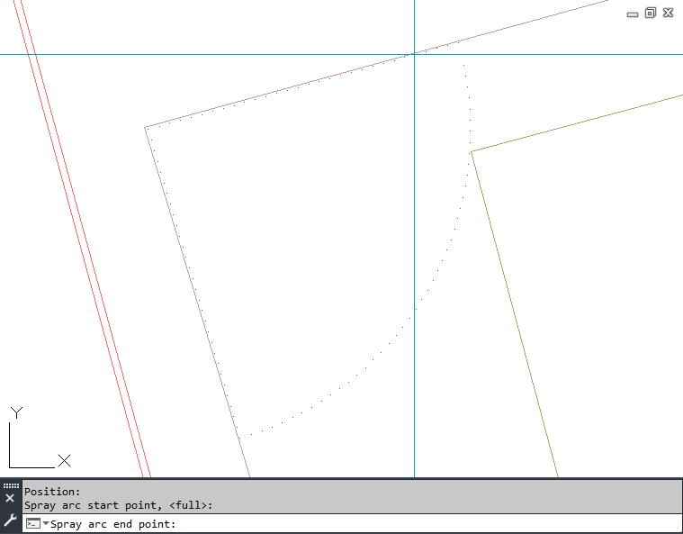
The keyboard commands are a valuable set of tools that allow you to jump quickly between different nozzle numbers and view the target differences for head placement.
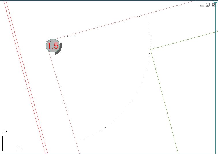
The rotor will be placed, and the arc you defined (if applicable) will appear.
If you selected one of our Arc Rotates or Symbol Rotates symbols for this rotor, you'll see an arc showing the spray direction.
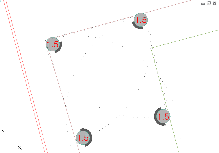
Here's an example of several rotors placed in a drawing:
Placing Impact Heads
An impact head revolves as the result of pressure from the water it emits, pivoting on a bearing on a threaded attachment nut. It also includes a spring that continuously pushes a sprinkler arm across the outgoing current of water, which results in even coverage. .
Open the Impact tool:
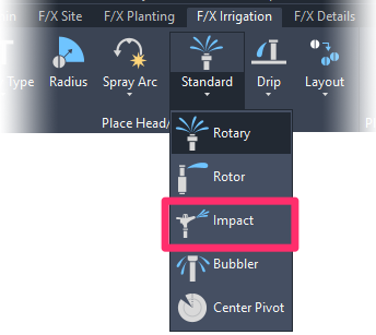
F/X Irrigation ribbon, Impact flyout

F/X Irrigation menu, Impact option
or type FX_PlaceImpact in the Command line
Placing Bubbler Heads
A bubbler delivers water via a small stream, which often conserves more water than a typical spray head.
Open the Bubbler tool:
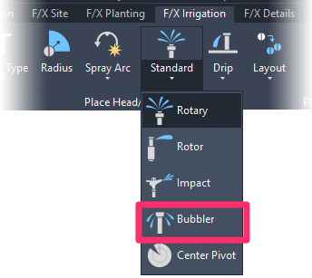
F/X Irrigation ribbon, Bubbler flyout

F/X Irrigation menu, Bubbler option
or type FX_PlaceBubbler in the Command line
Keyboard Commands for Placing Heads
We offer numerous handy keyboard commands for placing heads. For information and instructions, see our Keboard Commands for Placing Heads documentation.
Layout Tools for Placing Heads
Besides the keyboard command tools, which allow you to quickly jump between different nozzle radius or arc patterns, we offer a series of Layout tools to help you lay out and place heads quickly throughout your drawing. See our documentation sections on the following tools:
- Rectangular and Triangular Grid tools
- Rectangular and Triangular Array tools
- Copy Along Polyline
- Copy Along Line
- Match Head
- Match Properties
Editing or Viewing Information about Heads
The Edit Head / View Data tool allows you to see the model, flow, and design pressure of any selected head. This feature can be helpful in familiarizing yourself with a plan, or in finding out the flow required by an adjustable spray head. It also allows you to edit the design pressure, description, or nozzle. For more information, please see our Edit Equipment / View Data documentation.
Replacing Heads
The Replace tool, available in the Equipment Info dialog box, allows you to replace all instances of an existing head in your drawing with another model. For more information, please see our Replace Equipment documentation.
Many users run the Replace tool unnecessarily. Note that you can edit the text and model of any piece of equipment directly, without the need to use Replace.
General Information about Heads
For general information about sprinkler heads, see the Sprinkler Heads portion of our Irrigation Equipment Definitions documentation.
Changing the Symbols for Spray Heads in Your Projects and Drawings
If you've already added a particular head to your project – even if you've already placed it in a drawing – you may want to change its symbol to another one of our default symbols, or a version you've created. The method of changing out the symbol varies slightly between head types. See our documentation on changing symbols for irrigation heads.
Related Webinars
- Getting Started with Irrigation F/X: This tour and tutorial will help you make the most of everything Irrigation F/X has to offer. We start with the fundamentals, such as how to set up your projects and Preferences, before diving into our collection of time-saving irrigation design tools. (59 min)
- Irrigation for Beginners: We'll show how to navigate through the Irrigation ribbon and build a familiarity with our conceptual-level tools. You'll also learn the basics of adding equipment to a project, placing, piping, sizing, and scheduling. (1 hr 45 min)
Troubleshooting
Question: Is there a good way to show that a particular spray head is on a riser in an irrigation plan?
Issue: When I pipe to a head, the "snap" point is wrong
Issue: One of my heads is coming in oversized. All others seem to be fine.
Issue: Error accessing equipment data in the project
Issue: Wrong irrigation symbols coming in
Issue: When you place heads or other equipment, they are coming in at the wrong scale
Issue: You want to make the spray radius lines of your heads visible when you plot or plot preview
Issue: Heads in separate areas are connecting or sizing automatically
Issue: You need to rescale irrigation heads in your drawing to accommodate a new drawing scale
Issue: Heads' insertion points seem to be slightly offset from each other when placed
Issue: When placing a rotor, you are unable to see your desired nozzle size
Issue: Bad DXF group (10) error when placing irrigation equipment
Issue: Symbols for the model of head have different scales or sizes in your drawing
Issue: You changed the scale in your drawing, but new heads you place are not respecting the change
Issue: You are trying to switch from turf spray to shrub spray, but the symbols are not changing
Issue: You want to turn sprinkler arcs on once they are turned off
Issue: Rotor nozzle sizes are not visible in your plan but are visible in the Irrigation Schedule
Issue: Your heads are placing with the incorrect symbol family
Issue: Your irrigation head symbols are showing up with transparency when placed in your drawing
Issue: You saw a Missing File Error when attempting to place a head type besides a rotary head
Issue: You saw a Missing File Error when attempting to place a rotary head


